3 848 DESIGO™ RXC Controller with LONWORKS® interface RXC34.1/ALG Optimized for the control of room supply air and room extract air in laboratory rooms. The RXC34.1/ALG controller is used in conjunction with LONWORKS® communications for centralized room control functions. • LONWORKS® bus communications • 8 volt-free relay contacts (changeover contacts) • 8 analog outputs, DC 0…10V • 4 digital inputs for fast data acquisition, e.g. for meters (non-floating) • 14 universal inputs (DC 0...10V / 0...
Application The controller application is determined by downloadable application software, also referred to simply as the “application”. The application and its functions in relation to the RXC34.1/ALG is described in the RXC applications library (CA1100300). The RXT10 commissioning and service tool is used to download the application and to commission the RXC34.1/ALG (see "Commissioning"). The controller is delivered with laboratory application LAB02, for use in a laboratory environment.
Suggested enclosure supplier: Spelsberg): • Serial terminal enclosure RK 4/50 L, Order No. 616 950 01 (including DIN rail and cable gland) • or with transparent cover: TK empty housing PS 3625-11-tm, Order No. 106 012 01 (please order DIN rail and cable gland separately) Suggested contact guard: • Cover type AC2, supplied by Waldner Connection terminals Wago plug-in terminal blocks are used for the connection terminals. The RXC34.1/ALG comes with connectors without strain relief.
Engineering notes AC 24 V or DC 26 ... 35 V supply voltage STOP Caution The supply voltage for the RXC34.1/ALG must be volt-free. It is connected via plug-in terminal block X1 (terminals X1.1 and X1.2). • A supply voltage in excess of AC 29 V can cause damage to the device. • The supply voltage for the RXC34.1/ALG must not be earthed. Failure to comply with this instruction can cause damage to the device. • The power transformer must be volt-free on the secondary side.
EMC precautions • With the exception of the digital input cable, all connecting cables should be Digital inputs, fast counting The fast-counting binary inputs BE1 .. BE4 are used to read switch states and count switching pulses with a maximum switching frequency of 50 Hz. Only volt-free contacts may be connected to the binary inputs. The contacts are interrogated with approximately 24 V / 6 mA The maximum counter frequency is 50 Hz, defined by the software.
• • • • • • • The outputs generate voltages from DC 0 .. +10 V Maximum load current 5 mA 10-bit resolution The outputs are short-circuit-proof The outputs are non-floating Protective circuit: immunity up to +24 V Maximum load impedance: 2 kΩ Conductor crosssection Owing to the use of cage-clamp terminals, the cross-section of the connecting cables must not exceed 1.5mm2. EMC precautions • All signal cables must be screened • Every analog input connection should be a twisted pair.
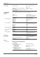
Technical data Power supply Operating voltage Current consumption with full configuration Internal fuse (This means that if the fuse blows, the controller must be replaced) Universal inputs, configured via the application All universal negative input terminals (–) are connected internally.
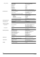
Analog outputs Ports/interfaces Number Output voltage Linearity error Offset error Gain error Resolution Load current Setting time Protective circuit 8 (AA1...AA8) DC 0...10 V, non-floating ± 2 bits = 20 mV 0.5 % ± 0.5 % 10 bits 5 mA Approx.
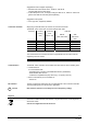
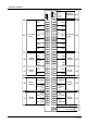
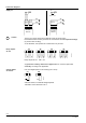
Connection terminals 1 - GND 2 - RxD 3 - RTS 4 - TxD 5 - CTS 6 - 12V DC 7 - 12V DC 8 - GND 1 1 ON + + + + + + + 14 13 12 11 10 9 8 7 6 5 4 3 2 1 14 13 12 11 10 9 8 7 6 5 4 3 2 1 + + + + + + + AA3/AA4 - 6 5 4 3 2 1 6 5 4 3 2 1 - AA7/AA8 + AA8 + AA7 AA5/AA6 + AA6 AA5 + 4 3 2 1 4 3 2 1 6 5 4 3 2 1 6 5 4 3 2 1 6 5 4 3 2 1 6 5 4 3 2 1 UE7 UE6 UE5 Universal X11 inputs UE4 UE3 UE2 UE1 X9 X7 Analog outputs Binary inputs + + AA1/AA2 + AA2 AA1 + AA4 AA3 BE2 BE1 BA6 X5 Binary outputs BA5 B
Connection diagrams +- Supply X1 X1 1 2 1 2 X1 DC 26 .. 35 V AC 24V +/- 15% 50/60Hz SP AC 24V +/- 15% 50/60Hz SN AC 230V 50/60 Hz STOP Caution The AC 24 V supply voltage for the RXC34.1/ALG and for the active transmitters/sensors must be generated via a transformer with two separate windings (to prevent short-circuiting). As an alternative, two separate 24 V transformers may be used. X3 X4 X5 X6 1 2 3 4 5 6 1 2 3 4 5 6 1 2 3 4 5 6 1 2 3 4 5 6 3848V02 Relay outputs X3...
Analog outputs X9 and X10 Each pair of analog outputs has a common ground (NOT G0!). (e.g. terminal X9.3 is ground for X9.1 and X9.2).
1 2 3 4 5 6 7 8 12 3 45 67 8 3848Z01 Service and diagnostics socket X13 Connector for extension modules X14 1 2 3 6 7 4 8 5 3848Z02 RJ45 9 RS232, D-SUB 9 1 2 3 4 5 6 7 8 9 GND RxD RTS TxD CTS +12V +12V GND -TxD+ RxD+ -GND -TxD– RxD– -- LONWORKS® bus connector The LONWORKS® bus connector, LONWORKS® service pin and the LONWORKS® node X15 status LED are located on the surface facing the terminal block.
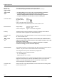
Dimensions 3848M01 All dimensions in mm 13/14 Building Technologies RXC34.1/ALG – Controller with LonWorks® interface CM2N3848en_02 12.01.
/14 © 2005 - 2007 Siemens Switzerland Ltd. Building Technologies RXC34.1/ALG – Controller with LonWorks® interface Subject to alteration CM2N3848en_02 12.01.