Induction Motors/ Generators Horizontal - Medallion 500, 580, 680, 800, 1120 Frames ODP, WPI, & WPII Enclosures Types CG, NCG, CGII, NCGII ANIM-03520-0110 (New Issue) ©2010 Siemens Industry, Inc. All rights reserved.
Table of Contents TABLE OF CONTENTS SAFETY PROCEDURES INTRODUCTION Warranty Receiving Handling Temporary Storage Type Designations Ventilation INSTALLATION Motor Dimensions Location Foundation Mounting Coupling of Sleeve Bearing Motors External Wiring Changing Direction of Rotation Alignment Hot Alignment Vibration Doweling Force Feed Lubrication Typical Motor Control Settings Page 1 2 3 3 3 4 4 4 4 5 5 5 5 5 5 6 6 6 7 8 8 8 9 OPERATION Initial Start Oil Circulating Systems Normal Operation Voltage/Frequ
Safety Procedures Do not operate this equipment in excess of the values given on nameplate or contrary to the instructions contained in this manual. The equipment (or a prototype) has been factory tested and found satisfactory for the condition for which it was sold. Operating in excess of these conditions can cause stresses and strains beyond design limitations. Failure to heed this warning may result in equipment damage and possible personal injury. This equipment contains hazardous voltages.
Introduction When receiving a motor with sleeve bearings: 1. Remove shaft blocking materials. 2. Visually inspect bearing condition through sight glass and bearing drain opening. 3. Check for moisture accumulation. Remove any traces of oxidation before putting the motor into service. 4. Fill bearing reservoirs to normal level with a high grade industrial lubricating oil. See Maintenance Section of this instruction book to determine proper oil level. 5.
Introduction Handling Type Designations Lifting devices are provided for handling only. experienced rigger should be used to install motors. An To avoid damage, the use of spreader bars is recommended on other than single point lifts. Lifting devices are provided to facilitate handling with shackles and cables. Avoid pounding or bumping shaft, coupling or bearing parts, as shocks may damage bearings.
Installation Motor Dimensions For motors built in the frame sizes covered by this manual, the letter dimensions have the same definitions as established NEMA standards. Established dimensions for these frames may be found on catalog sheets or certified drawings. CAUTION Before pouring, locate foundation bolts by use of template frame and provide secure anchorage (not rigid). It is recommended that a fabricated steel base be used between motor feet and foundation.
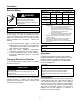
Installation External Wiring DANGER Motor Speed (No. of poles) Internal Rotor Cooling Fan 3600 – 3000 RPM 1800 RPM & Slower (2 pole) (4 or more poles) Rotor Material Aluminum Copper Aluminum Copper 1 4 3 3 N/A 4 N/A 3 N/A N/A N/A 2 500, 580 Frames 680, 800 Frames Hazardous voltage. Will cause death, serious injury, electrocution or property damage. Disconnect all power before working on this equipment. 1120 Frame 1. NOTE Before running motor, see Initial Start.
Installation Angular Alignment Hold each shaft at maximum end float. Rotate both shafts together, and measure between matching points at the outside diameter of the coupling faces for the top, bottom and both sides. Use two indicators because of possible axial shaft movement. Read difference of variation between them. 3. If no change is indicated, retighten the bolt and repeat the process for each of the remaining three mounting bolts. 4.
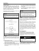
Installation Check for vertical alignment (parallelism) of coupled drive as follows: 1. Operate unit until normal temperature is reached (may require several hours). 2. Shut down motor and lock out switch. 3. Mount dial indicator as in Figure 2. 4. Rotate shaft, noting readings at 0°, 90°, 180°, and 270° (both sides, top, and bottom). If within 0.002 inch total indicator reading, or other limit specified by the factory, unit is satisfactory for operation. 5.
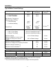
Installation Typical Motor Control Settings Alarm Trip (Shutdown) Winding Temperature • Class B Insulation • Class F Insulation 130°C 155°C 155°C 170°C Motor Bearing Temperature (Thermocouple or RTD’s) • Sleeve Bearing • Antifriction Bearing 100°C 100°C 105°C 105°C 4 Amps (2) Primary Circuit Ground Fault 8 Amps (2) Primary Circuit Timer Trip Setting (1) 0.2 sec. (2) Instantaneous Overcurrent • • With ½ Cycle Delay Without Time Delay 1.8 times Locked Rotor Amps (2) 2.
Operation Initial Start Oil Circulating Systems For motors with oil circulating systems, proceed as follows before startup; CAUTION Do not exceed number of Siemens specified hot and cold starts per hour. Will cause overheating. Allow time between starts to permit stator windings and rotor cage to cool. 1. Fill motor reservoirs to normal level (see motor outline drawing). 2. Follow instructions provided by the oil circulating system supplier. 3.
Operation Trouble Shooting DANGER Hazardous voltage. Will cause death, serious injury, electrocution or property damage. Disconnect all power before working on this equipment. Between regular maintenance inspections, be alert for signs of motor trouble. Common symptoms are listed in the following table. Correct any trouble immediately and AVOID COSTLY REPAIR AND SHUT DOWN. TROUBLE Motor will not start. POSSIBLE CAUSES CORRECTION Usually line trouble. Single phasing at starter. Check power source.
Operation Trouble Shooting DANGER Hazardous voltage. Will cause death, serious injury, electrocution or property damage. Disconnect all power before working on this equipment. TROUBLE Motor overheating (continued…) POSSIBLE CAUSES CORRECTION Open stator windings. Disconnect motor from load. Check idle amps for balance in all three phases. Check stator resistance in all three phases for balance. Air Recirculation. Check air intake and exhaust for obstructions. Check air inlet temperature.
Maintenance Preventive Maintenance Motors are designed to give many years of reliable service with a minimum of attention. Trouble-free operation cannot be expected if proper maintenance is postponed or neglected. Provide proper maintenance on the equipment. Follow carefully the instructions contained herein. Be certain personnel review, understand, and follow these procedures during periodic maintenance inspections. DANGER Hazardous voltage.
Maintenance Sleeve Bearing – 500, 580, 680, 800 Frames Access to the motor interior can be gained by removal of the upper half of the horizontally split bearing bracket. 1. Remove the parting bolts at the horizontal split. 2. Remove the bolts at the outer circumference of the upper half of the split-bearing bracket. 3. Pull the upper bracket away from the face of the frame and remove bracket.
Maintenance Vibration Most problems can be detected when inspected visually. Check for; 1. Loose or missing parts, such as fan blades, nuts, bolts, screws, couplings, etc. 2. Accumulation of dirt on fan or rotor. 3. Associated equipment - Disconnect equipment to determine where the vibration is being generated. 4. Foundation construction - Base, grouting and associated equipment supporting drives must be in good condition. Vibration can be amplified by weak construction.
Maintenance Insulation Resistance Check insulation resistance periodically. Use a hand cranked or solid state insulation resistance tester and test with at least 500 volts, but not greater than motor rated voltage. For motors with newer insulation systems such as MICLAD™ VPI, the insulation resistance after one minute should be greater than 1000 megohms. (Values in excess of 5000 megohms are common.) For older motors, the minimum value recommended in IEEE Standard 43 can be used.
Maintenance When this method is used on the stator, the stator phases may be connected in series or in parallel to suit the available power supply if both ends of all phases are accessible. If only three leads are brought out of the motor, the current may be circulated between one terminal and the other two connected together. If this is done, the temperature of the single lead connection must be checked frequently, and it is desirable to shift the leads occasionally.
Maintenance Insulated Bearings One or both bearings may be insulated to prevent shaft currents from pitting bearing surfaces. The insulation is located at the joint between the bearing housing or bracket and the bearing. Insulated bearings are designated by an instruction plate on the bearing housing. Check periodically to be sure the insulation has not been weakened or destroyed. The bearing insulation can be checked using an ohmmeter or circuit test light.
Maintenance At the first sign of oil discoloration or contamination, replace with new oil. Rapid discoloration is caused by bearing wear, often from vibration or thrust. Change oil as required to keep clean. important that the piping and venting for these oil seals be kept clean. NOTE When a sleeve bearing becomes worn and requires replacement, the labyrinth oil seal should also be replaced. When assembling the bearing, it is possible to foul the rings so that they will not turn freely.
Maintenance Sealing Parts Even though joints may seem to match perfectly, minute clearances exist through which oil may leak. . Apply sealant as follows: 1. Surfaces shall be clean of dirt, grease, and oil sealant. Use a non-oil base solvent if necessary. 2. The mating surfaces should be flat with no nicks raised above the surface. There should be no gap when mating surfaces are together. 3a. For 500, 580, and 1120 frames, apply a small bead of silicone RTV at the bearing housing parting surfaces.
Maintenance It is important to maintain the correct oil level, as lack of lubrication is often the cause of bearing failure. Sleeve Bearings CAUTION Maintain proper oil level. Failure to do so may cause improper lubrication of motor resulting in damage to the equipment. Follow lubrication instructions carefully. Avoid adding oil while unit is running. Motors with sleeve bearings are shipped without oil.
Maintenance Bearing Replacement Antifriction Bearings For typical antifriction bearing configuration, see Figure 3. Replacement bearings may be of a different manufacturer but must be equal to the originals used in the motor. When ordering bearings specify as follows: 1. The complete A.F.B.M.A. (Anti-Friction Bearing Manufacturers’ Association) bearing number from the motor nameplate. 2. Identifying numerals and manufacturer stamped on the bearing. 3. Bearing tolerance class, i.e. - A.B.E.C.
Maintenance Sleeve Bearing When replacing sleeve bearings, it is always desirable to check the fit (contact pattern) of the bearing to the shaft. When ordering sleeve bearings, be sure to provide complete motor nameplate and bearing data. If bearing is insulated, be sure to replace it with another insulated bearing. Whenever a bearing is replaced, cleanliness must be observed through every step of the operation. Always inspect the bearing journal surfaces; they must be smooth and polished.
Maintenance Sleeve Bearing 1120 Frame (See Figure 7) 1. Check replacement bearings for nicks or shipping damage. Do not scrape. 2. Carefully remove the bearing housing cap by first lifting straight up, then pulling away from the bearing area. 3. Remove top half of bearing liner. 4. Remove the bolts at the split line of the oil ring, disengage the dowels, and remove the oil ring. 5. Remove bearing temperature probes if so equipped. 6. Raise the shaft slightly and support it. 7.
Spare Parts Identification All units have an identification nameplate affixed to the frame (Figure 8). All the necessary information pertaining to the motor can be found on this plate including; 1. Serial Number 2. Type and Frame Size 3. Horsepower and Speed 4. Bearing Designations It is important when ordering spare parts or discussing service to have as much data from this plate as possible. Parts Identification Figures 9 through 16, are of a standard design. Your motor may differ slightly.
Spare Parts Figure 9. Type CG & NCG, 500 Frame Aluminum die cast rotor 1 2 3 4 13 12 12 6 11 7 9 8 5 10 14 15 Copper bar rotor 1 13 10 Item 1 2 3 4 5 6 7 8 Description Stator Core Stator Yoke Stator Coils Bearing Housing Rotor Shaft Inner End Cap Ball Bearing Shaft Seal 12 Item 9 10 11 12 13 14 15 For sleeve bearing parts see Figure 11.
Spare Parts Figure 10. Type CGII & NCGII, 500 Frame Aluminum die cast rotor 15 14 1 2 13 3 12 12 4 11 6 7 9 8 5 10 Copper bar rotor 1 13 10 Item 1 2 3 4 5 6 7 8 Description Stator Core Stator Yoke Stator Coils Bearing Housing Rotor Shaft Inner End Cap Ball Bearing Shaft Seal 12 Item 9 10 11 12 13 14 15 16 For sleeve bearing parts see Figure 11.
Spare Parts Figure 11.
Spare Parts Figure 12. Types CG & CGII, 580 Frame 15 1 14 2 4 3 13 12 12 12 11 7 9 8 5 6 10 Copper bar rotor 1 13 10 Item 1 2 3 4 5 6 7 8 12 Description Item Stator Core 9 Stator Yoke 10 Stator Coils 11 Bearing Housing 12 Rotor Shaft 13 Inner End Cap 14 Ball Bearing 15 Shaft Seal For sleeve bearing parts see Figure 13.
Spare Parts Figure 13.
Spare Parts Figure 14. Types CG & CGII, 680 & 800 Frames 16 15 1 2 13 3 14 14 4 12 9 7 10 8 6 11 13 Item 1 2 3 4 5 6 7 8 Description Stator Core Stator Yoke Stator Coils Bearing Housing Rotor Shaft Inner End Cap Ball Bearing Shaft Seal Item 9 10 11 12 13 14 15 16 For sleeve bearing parts see Figure 15.
Spare Parts Figure 15.
Spare Parts Figure 16.
Motor Service Record ______________________ Horsepower ______________ Type ___________ Serial No _____________ Amperes _____________ Hertz _______ Speed ________ Volts Insulation Class _______ Owner Order No _________________ MACHINE TYPE Horizontal Vertical (1) Name of Part Item No _______ _____ °C BEARINGS Ball Roller Sleeve Length ___________________ Diameter _________________ Internal Thread ____________ External Thread ____________ Keyway __________________ Application R
Vibration Analysis Sheet Pick-Up Point Position Horizontal Vertical Axial Horizontal Vertical Axial Horizontal Vertical Axial Horizontal Vertical Axial Horizontal Vertical Axial Horizontal Vertical Axial Horizontal Vertical Axial Horizontal Vertical Axial Horizontal Vertical Axial Horizontal Vertical Axial Horizontal Vertical Axial Disp. Mils Filter-Out Coupled Freq* Vel. Freq.* CPM In/Sec CPM Vel. Mils Freq. CPM Vel. Mils Filter-In Coupled Freq. Vel. Freq. CPM Mils CPM Vel. Mils Freq.
Notes __________________________________________________________________________________________ __________________________________________________________________________________________ __________________________________________________________________________________________ __________________________________________________________________________________________ __________________________________________________________________________________________ __________________________________________________
Siemens Industry Drive Technologies Division Norwood Motor Plant 4620 Forest Avenue Norwood, OH 45212-3396 (513) 841-3100 ANIM-03520-0110 (New Issue) ©2010 Siemens Industry, Inc. All rights reserved.