
Specifications

Positioning IP 240
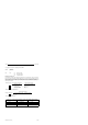
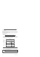
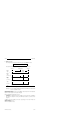
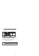
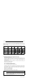
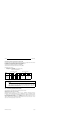
The table below shows the contents of the data block for a zero offset.
A negative value must be spe-
cified as two's complement.
SE=Sign extension
The high-order nibble of DL 46
(SG) must be ”1111” for a nega-
tive number.
ADD=0 for relative NVER, ADD=1 for additive NVER
0
0
SE
2
19
2
11
2
3
0
0
SE
2
18
2
10
2
2
0
0
SE
2
17
2
9
2
1
0
SE
2
16
2
8
2
0
Binary representation BCD representation
DL 45
DR 45
DL 46
DR 46
DL 47
DR 47
0
0
SE
2
20
2
12
2
4
0000
000
10
6
10
4
10
2
10
0
0000
0000
SG
10
5
10
3
10
1
Bit
7 6 5 4 3 2 1 0
Bit
7 6 5 4 3 2 1 0
Data
byte
0
0
SE
2
21
2
13
2
5
0
0
SE
2
22
2
14
2
6
0
0
SE
2
23
2
15
2
7
ADD
ADD
After configuring and after every synchronization, the actual value is set to the value of the last
zero offset transferred, irrespective of whether the zero offset was relative or additive.
If you configured a channel for a rotary axis and transferred a negative zero offset, the actual
value is set to the value [final value for the rotary axis] + [negative zero offset].
Example: Final value of the rotary axis = 10,000
Zero offset = - 2,000
Actual value after synchronization = 8,000
Note
After configuring, you can transfer relative or additive zero offsets in any order.
Note, however, that, after an additive zero offset, the next relative zero offset sets
NVER
rel.,old
to 0 ( Section 10.18.3).
10-28
EWA 4NEB 811 6120-02a