
Specifications


Module Description and Accessories IP 240
2.2.3 Inputs/Outputs
The IP 240 provides two options for connecting sensors to the pulse inputs:
• All sensor signals can be routed to the 15-pin subminiature D socket connectors X2/X4
( Section 4.2.2)
• Clock signals up to 10 kHz can also be routed over the 7-pin plug connectors X3/X5
( Section 4.2.2).
The sensor power supply is only available at the 15-pin subminiature D socket connectors.
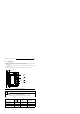
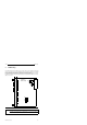
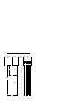
Fig. 2-1. Front Connectors
X4
X2
Pulse
Inputs
Shield potential
Digital outputs
Binary inputs
5 V
S5 bus
L+
M (L -)
Pulse
Inputs
Channel 1
Channel 2
Digital outputs
Binary inputs
Channel 1
Channel 2
X3
X5
X6
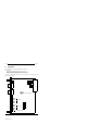
Position
decoding
Counting
IP 252-
expansion
Positioning
M
int
Warning
To ensure noise immunity, all inputs, outputs and the 24 V supply on the IP 240
must be connected using shielded, twisted-pair cables.
Terminal M (L-) is connected on the IP 240 to the module ground (M
int
).
Inputs
Terminals A and A A* IN (prelim. contact)
B and B B* CLK (CLOCK)
Z and Z Z* GT (GATE)
Encoder signals Symmetrical Asymmetrical
(RS 422 A)
Rated voltage 5 V 24 V 24 V
Galvanic isolation no no no
2-4
EWA 4NEB 811 6120-02