
Specifications

Position Decoding IP 240
Example:
The position encoder emits 1000 pulses/revolution. The spindle has a gradient of 50 mm/revolu-
tion. The position encoder therefore emits 1000 pulses for a distance of 50 mm. The IP 240 pro-
cesses up to 199,998 increments within the defined actual value range. This results in the
following traversing ranges:
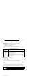
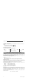
Table 7-1. Sample Traversing Ranges
Resolution Simple Twofold Fourfold
Traversing range
Traversing distance/increment
9,999.9 mm 4,999.9 mm 2,499.9 mm
25 µm 12.5 µm50 µm
7.2.3 Reference Tracks
Up to eight reference tracks can be defined for cam simulation by specifying initial and final
values ANF1 to ANF8 and END1 to END8. In every module firmware cycle, the limit values are
compared with the actual value. If the actual value is within a track (including track limits), a
status bit REFn is set.
Identical and overlapping reference tracks are possible. A minimum track width of one increment
(ANFn=ENDn) is permissible.
Entering limit values in the data block
Data words DW 34 to 65 are reserved in the data block for the input of limit values. Two data
words are provided for every limit value.
The limit values must be entered in BCD code within a range of - 99,999 to+99,999.
The initial value ANFn of a track n must be smaller than or equal to the final value ENDn of
track n.
Otherwise the corresponding bit REFn is not set for any actual value.
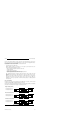
Tables 7-2 and 7-3 show the data format in which the limit values must be entered, in this case for
track 1.
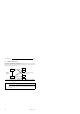
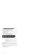
Table 7-2. Initial Value of the First Track (ANF1)
7 6
DL 34
DR 34
DL 35
DR 35
Data
word
5 4 3 2 1 0
0
0
0
0
0
Bits
0
0
0
0
10
4
0 0 SG
10
3
10
1
10
2
10
0
SG = 1 the initial value is negative
= 0 the initial value is positive
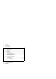
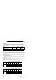
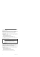
Table 7-3. Final Value of the First Track (END1)
7 6
DL 36
DR 36
DL 37
DR 37
Data
word
5 4 3 2 1 0
0
0
0
0
0
Bits
0
0
0
0
10
4
0 0 SG
10
3
10
1
10
2
10
0
SG = 1 the initial value is negative
= 0 the initial value is positive
7-4
EWA 4NEB 811 6120-02a