KINCO CONTENTS MT5000/4000 SERIES HMI AND PLC CONNECTING GUIDE ............................................................ 3 SERIAL COMMUNICATION PIN DEFINITION................................................................................................... 3 PARALLEL PORT PIN DEFINITION ................................................................................................................. 3 PRINTER CONNECTING CABLE DIAGRAM ......................................................................
KINCO Koyo Corporation................................................................................................................................ 122 KTC Srdlink ........................................................................................................................................ 125 LENZE Inverter................................................................................................................................... 127 LS Industrial Systems Co., Ltd. .....................
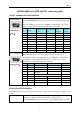
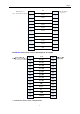
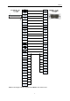
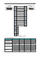
KINCO MT5000/4000 Series HMI and PLC connecting guide Serial Communication Pin definition Pin Designations Pin assignment of the 9-pin male, D-SUB, COM0/COM2. This port is used to connect MT5000/MT4000 series touch screens and provides RS-232/485/422 port. Note: The COM2 port is used for programming and debugging, and it is also used for communication, but only provides RS-232 port controller.
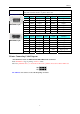
KINCO HMItek Ltd. will continuously provide drivers for various brands of printers. Note: The maximum distance of printer cable is 5m.
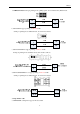
KINCO Printer 26 pin port Note:the red line is the first pin STB 1 5 DATA1 3 4 DATA2 5 13 ERROR 4 15 DATA3 7 8 DATA4 9 3 DATA5 11 12 DATA6 13 7 DATA7 15 2 DATA8 17 11 BUSY 21 10 GND 10 The MT5000 series touch screens cable diagram:As follows 2.
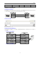
KINCO a. WH4008A31-053 Serial port printing mode, pulling up W1 short circuit block by RS232 level. b. WH-A62R10 support printing of 190 dots width. Serial port printing mode via RS232 level, short circuit as follows: c. WH-A52Z20-30E125 support printing of 240 dots width. Serial port printing mode via RS232 level, short circuit as follows: d. WH-A93RG0-00E825 now support printing of 384 dots width Serial port printing mode via RS232 level, short circuit as follows: 3. Siupo Printer cable a.
KINCO 4.
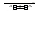
KINCO Printer series 25 pin convert to 15 pin of the MT4300 series touch screen 8
KINCO 5.
KINCO WH-A93RG0-00E825 WH-A93RG0-00E825 Serial thermal 384 dots/line SP-M, D, E, F SP-E4004SK Serial Stylus micro printer 240 dots/line Download Cable Diagram Download by Serial Port The COM2 port on the back of the case can be used to connect PLC RS-232 devices and can also be used to connect with the programming interface and setting interface of a PC.
KINCO HMI Ethernet terminal RJ45 1 TX+ 2 TX3 RX+ 4 BD4+ 5 BD46 RX7 BD3+ 8 BD3- Ethernet Hub or Switch RJ45 (orange,white) ( orange) (green,white) (bule) (bule,white) (green) (brown,white) (brown) 1 RX+(orange,white) 2 RX- (orange) 3 TX+ (green,white) 4 BD4+ (bule) 5 BD4- (bule,white) 6 TX(green) 7 BD3(brown,white) 8 BD3- (brown) Communication Settings and guide of HMI connecting with Controller Note:Don’t live plug! ABB Corporation Serial Communication Series CPU Link Module ABB AC31 O7KR51-V3.
KINCO RS485 ABB AC500:Default communication parameters 9600, 8, none, 1; station No.
KINCO Supported Device ABB AC31 Device Bit Address Word Address Format Input bit I00.00-68.15 ------ DD.DD Output bit O00.00-68.15 ------ DD.DD M(0.0--99.15)U(233.00-255.15) ------ DDD.DD S000.00-125.15 ------ DDD.DD Input Register ------ IW00.00-68.15 DD.DD Output Register ------ OW00.00-68.15 DD.DD Internal Register ------ MW(0.0--99.15)U(233.00-255.15) DDD.DD Indirect Register ------ KW01.00-31.15 DD.DD Internal Register (Double words) ------ MD0.00-7.15 D.
KINCO ABB AC31 RS485 ABB AC500 port1 RS232 ABB AC500 port2 RS232 Allen-Bradley Serial Communication Series CPU MicroLogix (1764-LRP) MicroLogix SLC500 1500 Link Module Driver Channel 1 AB DF1 MicroLogix 1000 MicroLogix 1200 MicroLogix 1500 (1764-LSP,1764-LRP) Channel 0 MicroLogix 1400 (1766-L32BWAA) Channel 0 SLC 5/03 SLC 5/04 SLC 5/05 Channel 0 AIC+ Advanced Interface Converter 1761-NET-AIC Channel 2 1770-KF3 2760-RB 1775-KA 14
KINCO 5130-RM 1771-KGM PLC-5 PLC-5/11 PLC-5/20 PLC-5/30 PLC-5/40 PLC-5/40L PLC-5/60 PLC-5/60L Channel 0 CompactLogix 1769-L20 1769-L30 1769-L31 1769-L32E 1769-L35E Channel 0 Channel 1 AB CompactLogix/ControlLogix ControlLogix 1756-L61 1756-L63 CPU Direct AB CompactLogix/ControlLogix Ethernet Communication (Direct Online Simulation disable) Series MicroLogix SLC500 PLC-5 CPU Link Module Driver MicroLogix 1100 MicroLogix 1400 CPU Direct (channel 1) MicroLogix 1000 MicroLogix 1100 MicroLo
KINCO MicroLogix 1400 Channel 0 Channel 2 Your owner cable RS232C Setting RS232C Setting Your owner cable RS232C Setting Your owner cable RS232C Setting Your owner cable RS232C Setting Your owner cable Connect Type Parameter Cable Ethernet Setting Your cable Your owner cable Channel 0 SLC500 SLC 5/03 SLC 5/04 SLC 5/05 1770-KF3 2760-RB 1775-KA 5130-RM 1771-KGM PLC-5 PLC-5/11 PLC-5/20 PLC-5/30 PLC-5/40 PLC-5/40L PLC-5/60 PLC-5/60L CompactLogix 1769-L20 1769-L30 1769-L31 1769-L3
KINCO SLC500 RS232 communication CompactLogix/ControlLogix RS232 communication 17
KINCO PLC Software Setting a. RSLogix500 software setting Note: Driver: DF1 Full Duplex; Error Detection: CRC. b. RSLogix5000 software setting Note: Protocol: DF1 Point to Point; Error Detection: CRC; Enable Duplicate Detection: Disabled.
KINCO Note: Define the new device in the RSLogix5000 before using the register in the HMI. (2) Define Tags and Data type: select “controller tags” right-click—>”edit tags”, set up Tags: Note: When the Data Type isn’t defined data array, only one address is available to use; how to define the Tag Number, you can refer to the RSLogix5000 manual. (3) Assign the Tag Name created by RSLogix5000 to the optional File Name: select “logic”--->”map PLC/SLC messages”.
KINCO PLC configuration Supported Device MicroLogix 1200 Device Bit Address Word Address Format Bit data file B10:0.0-254.15 ------ DDD.DD Bit data file B3:0.0-254.15 ------ DDD.
KINCO Output data file O0:0.0-0.63 ------ DD.DD Input data file I1:0.0-0.63 ------ DD.
KINCO Integer data file ------ N11:0-255 DDD Integer data file ------ N10:0-255 DDD Integer data file ------ N7:0-255 DDD Integer data file ------ Nf:n:0-255255 FFFDDD Floating point data file ------ F8:0-255 DDD Floating point data file ------ Ff:n:0-255255 FFFDDD Counter Accumulator Value ------ C5PV:0-255 DDD Counter Preset Value ------ C5SV:0-255 DDD Timer Accumulator Value ------ T4PV:0-255 DDD Timer Preset Value ------ T4SV:0-255 DDD *1 *1 Note: 1.
KINCO PLC-5 RS232 cable diagram HMI terminal 9pin D-SUB female/male Controller terminal 25 pin D-SUB male com0/com1 com2 2 RX 7 RX 3 TX 8 TX 5 GND 5 GND 2 TXD 3 RXD 7 SG 4 RTS 5 CTS 6 DSR 8 DCD 20 DTR CompactLogix/ ControlLogix RS232 cable diagram EtherNet cable Connecting PC and HMI use cross-ruling; communicating with hub or switch use Cross-over cable or cross-ruling. a. cross-ruling cable diagram: b.
KINCO HMI Ethernet terminal RJ45 1 TX+ 2 TX3 RX+ 4 BD4+ 5 BD46 RX7 BD3+ 8 BD3- Ethernet Hub or Switch RJ45 (orange,white) ( orange) (green,white) (bule) (bule,white) (green) (brown,white) (brown) 1 RX+(orange,white) 2 RX- (orange) 3 TX+ (green,white) 4 BD4+ (bule) 5 BD4- (bule,white) 6 TX(green) 7 BD3(brown,white) 8 BD3- (brown) ACS-Tech80 Motion Controller Serial Communication Series CPU Link Module Driver SA2103 SB214SA RS232 on the CPU unit ACS-Tech80 System configuration Series CPU Link
KINCO Device Bit Address Word Address Format Notes LD 0~3 D R/W Linear Acceleration(LA) ----------- LA 0~3 D R/W Linear Velocity(LV) ------ LV 0~3 D R/W Next trgt Abs Pos(AP) ------ AP 0~3 D R/W Next Motion Mode(MM) ------ MM 0~3 D R/W Functions Avail.(FA.1) ------ FA.1 0~3 D Read Only Array Offset(AO) ------ AO 0~3 D R/W Array’s Upper Index(UI) ------ UI 0~3 D R/W Array’s Low Index(LI) ------ LI 0~3 D R/W Path Gen.
KINCO System configuration Series CPU Link Module COMM Type Parameter Cable ADAM-4017 RS485on the CPU unit RS485 Setting Your owner cable ADMA-4015 RS485 on the CPU unit RS485 Setting Your owner cable ADAM Communication Setting HMI ADAM-4017 default communication: 9600, 8, none, 1; station: 255 Note:a. To allow the “Check Code”; b. Direct online simulation disables.
KINCO Set OK, then Update.
KINCO 255(FF):0-7 channel show. 127(7F):0-6 channel show, 7 Channel does not show. ADAM-4015 Device Bit Address Word Address Format Notes Channel ------ Channel 0-5 D Floating Note: Channel 0-5 data type is floating.
KINCO Supported Device Device Bit Address Word Address Format Notes control CTL (0~5)&128&150 ------ DDD Write only set ------ SET (0~51)&128 DDD state ------ STATUS 0.0~17.2 DD.
KINCO Communication Setting PLC software setting Use the guide of the Workbench software 30
KINCO Supported Device (Only data of comms can be monitored, some address greater than or equal to 100 are read only. Please pay attention to matching the controller software configuration.
KINCO Barcode Serial Communication Series CPU Link Module Driver Barcode 3800LTP-12E RS232 Barcode System configuration Series CPU Link Module COMM Type Parameter Cable Barcode 3800LTP-12E RS232 RS232 Setting Your owner cable Communication Setting Supported Device Device Bit Address Word Address Format Word -------- LW 0-8999 DDDD Word -------- LW 9000 DDDD Notes Note: 1. LW0-8999: the character after scanning, text and note book parts can display it. 2.
KINCO Baumuller Serial Communication Series CPU Link Module Driver Baumuller BM4413-ST0-02200-03 RS422 on the CPU unit Baumuller System configuration Series CPU Link Module COMM Type Parameter Cable Baumuller BM4413-ST0-02200-03 RS422 on the CPU unit RS485 Setting Your owner cable Communication Setting Supported Device Device Bit Address Word Address Format Bit type DB_BIT0.00-255.F ------ DDD.H Word type ------ DB0-255 DDD Example: DB2_BIT address please input 0.
KINCO HMI terminal 9pin D-SUB female\male Controller terminal 9 pin D-SUB (male) com0/com1 9 TXD+ 4 TXD6 RXD+ 1 RXD5 GND 6 RXD+ 5 RXD9 TXD+ 1 TXD3 GND Bosch Rexroth KVFC+ (Frequency Converter) Serial Communication c CPU KVFC+ Link Module Driver RS485 Bosch Rexroth KVFC+ System configuration Series CPU KVFC+ Link Module COMM Type Parameter Cable RS485 on the CPU unit RS485 Setting Your owner cable Communication Setting Supported Device Device Bit Address Word Address Format Start/
KINCO STW1 close, positive rotation. STW1 open, negative rotation. STW2 REV inching turning. STW3 FWD inching turning. Set frequency ------ HSW 0 D Basic Function Block ------ B 0~41 DD Deviation alarm ------ E 0~41 DD ------ P 0~37 DD High function array ------ H 0~38 DD D array ------ D 0~6 D Programmable control B16 acceleration time. B17 deceleration time. function array D0: output power. D2: running current.
KINCO Communication Setting PPC-R communication setting RS232 communication: 19200, 8, even, 1; station number: 128 RS485 communication Note: To communicate with the touch screen, declare variable firstly in the Rexroth software. L40 communication settings Default communication: 38400, 8, 1, none; Station No.
KINCO Note: To communicate with the touch screen, declare variable firstly in the Rexroth software. L40 Hardware Settings PLC Software Settings PPC-R software setting PLC connects with PC via crossover ethernet cable.
KINCO 1.Click”scp configurator”--->”scanning ”or” add device”--->”next”, pay attention to the default controller IP: 192.168.1.1. And set IP 192.168.1.1 in the software (PC and controller must be set up in the same segment), ping IP address is OK, that configuration is successful. Save and close “scp configurator”--->”refresh” to see logical devices created in configured logical devices”, double-click to enter. All configurations will be successful. 2.
KINCO 4. Click “online/login” L40 software setting 1) The IndraLogic software connect with the Rexroth IndraControl L40 by ethernet cable(test: plc IP address:192.168.100.
KINCO Note:Must select Download symbol file Click “OK” and pop-up the window as follows: And then edit program: Input B0 and pop-up the dialog, configurations as follows, click “OK”: 40
KINCO And set up coil: At the same time, you will find that there automatically generate two variables in the global variable: Then setting as follows: 41
KINCO Setting communication parameter: Then click “Login”: Communicating successfully, you can operate(“Online” menu to select “run” or others): 42
KINCO Note:The PLC panel must be set up, press” Enter”, then press”△”, until showed up “ RS232”, and then press ”Enter” to enter “COM SERV” interfaces (not SERV, it must change to SERV) In accordance with the above settings, the serial line access, EV5000 can be communicated with the Rexroth Controller L40 by serial port.
KINCO L40 communication cable Bosch Rexroth Ethernet Network communication (indirect online and direct online simulation disable) Series CPU Link Module Driver IndraLogic IndraLogic L40 DPM ETH on the CPU unit Bosch Rexroth Ethernet System configuration Series CPU Link Module COMM Type Parameter Cable IndraLogic L40 DPM 02VRS ETH on the CPU unit ETH Setting Your owner cable Communication Setting Network communication ※Project construction ※HMI Attribute 44
KINCO ※PLC Attribute (station disable) ※Network configuration(Note: PLC port num. must be set 6042,HMI port num. is optional,default is 6042. In addition, the screen and plc must be set in the same network segment, the gateway of the screen is better to set with the actual use of the network gateway .
KINCO Note: To communicate with the touch screen, declare variable firstly in the Rexroth software. PLC software setting PLC connect with PC by crossover network cable,if using cross-connection network cable, you must add a HUB (we usually use a cross-connection line to access the Internet) 1.
KINCO 2. “”resource”--->“Global variables”--->declare variable in “HMI” 3. Click “online/login” Supported Device Device Bit Address Word Address Format BYTE B0000-9999 ------ DDDD WORD ------ W0-65535 DDDDD INT ------ I0-65535 DDDDD UINT ------ UI0-65535 DDDDD DWORD ------ DW0-65535 DDDDD DINT ------ DI0-65535 DDDDD UDINT ------ UD0-65535 DDDDD Notes Cable Diagram Cross-connection or crossover network cable can be used as communication cable via the hub a.
KINCO b.
KINCO HMI Note: Baud Rate and Station No. must be the same as the setting in the controller. PLC setting Note: you can find MT5020.EDS in fieldbus file of EV5000 Installation Directory, or you can download from www.kinco.cn. Take MT6000 for example (we use MT6000 HMI to test, and use 3S CODESYS software to download project) 1. Setup z Start Menu “3s Software”->“Codesys v2.3”->“installtarget” z Click “open” choose “StepServoARM.tnf”, and then click “install”.
KINCO 2. Copy “MT5020.EDS” to “C:\Program Files\Common Files\CAA -Targets\ StepServo\ PlcConf” 3. Configuration setting a. run codesys software,make a new project b.
KINCO c. set Baud Rate d. choose “CanMaster” right click “Append HMI-MT5020” e. Node ID: set slave station No.
KINCO f. in the “Library Manager” we import “3S_CANopenMaster.lib” g.
KINCO h. define Global Variable i.
KINCO j.
KINCO Danfoss Inverter Serial Communication Series CPU Link Module Driver Danfoss FC-300 RS485 on the CPU unit Danfoss Modbus RTU System configuration Series CPU Link Module COMM Type Parameter Cable Danfoss FC-300 RS485 on the CPU unit RS485-2 Setting Your owner cable Modbus RTU FC-300 RS485 on the CPU unit RS485-2 Setting Your owner cable Communication Setting Danfoss Protocol: Modbus RTU Protocol: 55
KINCO Note:Change the value of 8-30 to 2 on the Danfoss Frequency Converter for modbus protocol (Change the value of 8-30 to 0 for the Danfoss Protocol) Frequency Converter 8-3* FC Port Setting 8-30 protocol *[0] FC (danfoss protocol) [2] Modbus (modbus protocol) 8-31 address 1 – 247 * 1 (HMI station No.
KINCO RAM Register(Double Word) ———— RMD0-7998.99999 DDDD.DDDDD RAM Register ———— RMW0-7998.99999 DDDD.DDDDD Note: 1. D indicates decimal; the prefix of RMD\RMW\EPD\EPW is address parameter, the suffix is index number. 2. Mapping of index address (adding radix point if having index address, index value follow radix point. Otherwise there’s no radix point): RMW310.1 is to 3-10, please clicking Menu, to find 3-10 to check. 3. If no index, radix point followed by default zero.
KINCO ◆Control word RW1: While RW1=0x47C or 1148, it means start. While RW=0x0F03 or 3843, it means stop. ◆Frequency of RW0 mapping : If input 2000 to RW0, frequency is 25HZ, and input 4000, frequency is 50HZ, and so on. ◆Timer, send value of RW1 and RW0 to RWD8000.
KINCO Input bit (read only) 1X1-65535 ------ DDDDD Input Register (read only) ------ 3X1-65535 DDDDD Output Register ------ 4X1-65535 DDDDD Note: Mapping of address (same as *10 relationships): 2-01 is to 4X2010 3-02 is to 4X3020 So address 4X1300 is to 1-30 as following picture, here is double word address. To get more information, please refer to danfoss manual.
KINCO Set 0X 3,0X 4,0X 5,0X 6,0X 7 all to “1” via the method of setting on when window open; Change the frequency inverter status (start or stop) by control the status of 0X11. 0x2000=0010 0000 0000 0000(binary bit from the 17th to the 32nd), setting the 30th bit to “1” means frequency is 25Hz, and “1” in the 29th bit means 12.5Hz, and so on. In short, the 0X17~0X32 is to control frequency. The Frequency Converter will show the value after starting.
KINCO HMI terminal 9pin D-SUB female\male Controller RS485 terminal com0/com1 1RX6RX+ 5 GND 69 68 61 Delta Corporation Serial Communication Series CPU Link Module DVP DVP14SS11R2 DVP 24 DVP 32 DVP 60ES00 DVP-XXES01 Driver RS232 on the CPU unit Delta DVP RS485 on port System configuration Series CPU DVP DVP14SS11R2 DVP 24 DVP 32 DVP 60ES00 DVP-XXES01 Link Module COMM Type Parameter Cable RS232 on the CPU unit RS232 Setting Your owner cable RS485 on port RS485-2 Setting Your owner
KINCO DVP RS485-2 communication Note: if we use RS485 communication, we should change the value of D1120 in the PLC Software. PLC setting 1. Wpl207->Auxiliary Editing->RS-485 Protocol Setting (D1120), you can set the value of D1120.
KINCO 2. when PLC and Wpl207 are connective, change D1120. for example, 9600,7,even,1.
KINCO Delta (Temperature Controller) Serial Communication Series DVP CPU Link Module Driver DTA4848 RS485 on the CPU unit DTB9696VR RS485 on the CPU unit Delta DTA_DTB System configuration Series CPU Link Module COMM Type Parameter Cable DVP DTA4848 RS485 on port RS485-2 Setting Your owner cable DTB9696VR RS485 on port RS485-2 Setting Your owner cable Communication Setting RS485-2 communication Note: Only use 4X, not 3X in the ev5000 project.
KINCO Device Bit Address Word Address Format Output bit 0X1-65535 ------ DDDDD Input bit (read only) 1X1-65535 ------ DDDDD Input Register (read only) ------ 3X1-65535 DDDDD Output Register ------ 4X1-65535 DDDDD Notes Controller Setting 1. Set the communication parameter Setting communication parameter in “setting mode” (1) (Station number) matching the station No.
KINCO range. In the setting mode 4707H Lower-limit range of temperature The data content should not be lower than the temperature range. In the setting mode 4708H PB Proportional band 1 to 9999, unit is 0.1. In the adjusting mode 4709H Ti Integral time 0~9999. In the adjusting mode 470AH Td Derivative time 0~9999. In the adjusting mode 470BH Heating/Cooling hysteresis 0~9999 4710H Input temperature sensor type In the setting mode 0: PID (default), 1: ON/OFF, 2: manual tuning.
KINCO 4729H AT Setting OFF: 0 (default), ON: 1. in the adjusting mode 4733H CT monitor value Unit is 0.1A. in the running mode DTB9696VR:Address and Content of Word Register (corresponds to 4X in the HMI) Address Content Explanation 1000H Process value (PV) Measuring unit is 0.1, updated one time in 0.4 second 1001H Set point (SV) Unit is 0.1, oC or oF The data content should not be higher than the 1002H Upper-limit of temperature range temperature range.
KINCO 100FH The setting of Dead band when Dual Loop output control are used -999 ~ 9,999. in the adjusting mode 1010H Hysteresis setting value of the 1st output group 0~9999. in the adjusting mode 1011H Hysteresis setting value of the 1st output group 1012H 1013H 1014H 1015H Hysteresis setting value of the 1st output group Hysteresis setting value of the 2nd output group Upper-limit regulation of analog linear output Lower-limit regulation of analog linear output or 0~9999.
KINCO In the setting mode 1024H Upper-limit alarm 1 In the setting mode 1025H 1026H unit: 0.1 Lower-limit alarm 1 In the setting mode Upper-limit alarm 2 In the setting mode 1027H Lower-limit alarm 2 In the setting mode 1028H Upper-limit alarm 3 In the setting mode 1029H Lower-limit alarm 3 In the setting mode 102AH Read LED status b0 : Alm3, b1: Alm2, b2: F, b3: ℃, b4: Alm1, b5: OUT2, b6: OUT1, b7: AT 102BH Read pushbutton status b0: Set, b1: Select, b2: Up, b3: Down.
KINCO 0810H Communication write-in selection Communication write in disabled: 0 (default), Communication write in enabled: 1. In the setting mode 0811H o Temperature unit display selection C/linear input (default): 1 , oF : 0. in the setting mode 0812H Decimal point position selection Except for the thermocouple B, S, R type, all the other thermocouple type are valid. (0 or 1). In the running mode 0813H AT setting OFF: 0 (default), ON : 1.
KINCO D3CellTM Serial Communication Series CPU Link Module Driver D3CellTM D3CellTM RS422 on the CPU unit DLoadCell System configuration Series CPU Link Module COMM Type Parameter D3CellTM D3CellTM RS485 on the CPU unit RS422 Setting Supported Device For detailed device, please refer to the PLC manual.
KINCO EB-MOD2P-01(Bus Bridge) Serial Communication Series CPU Link Module Driver RS232 on the CPU unit FieldBus Bridge EB-MOD2P-01 RS485 on the CPU unit EB-MOD2P-01 RS422 on the CPU unit System configuration Series FieldBus Bridge CPU EB-MOD2P-01 Link Module COMM Type Parameter RS232 on the CPU unit RS232 Setting Your owner cable RS422 on the CPU unit RS422 Setting Your owner cable RS485 on the CPU unit RS485 Setting Your owner cable Communication Setting EB-MOD2P-01 RS232 commu
KINCO EB-MOD2P-01 RS485-2 communication Supported Device EB-MOD2P-01 Device Bit Address Word Address Format Internal/External Output bit 0X1-60 ------ DDDDD Internal/External Input bit 1X1-60 ------ DDDDD Data Register bit 3X_bit1-60 ------ DDDDD Data Register bit 4X_bit1-60 ------ DDDDD Simulate Input Register bit ------ 3X1-60 DDDDD Data Register ------ 4X1-60 DDDDD Data Register ------ 5X1-60 DDDDD Data Register ------ 6X1-60 DDDDD Data Register ------ 3X-DINV 1-60
KINCO Note:The correspondence between the device of EV5000 and the s7-300 software, as follows: 4X-DINV------------PID e.g.:4X-DINV1------------PID256 4X-DINV3------------PID260 3X-DINV------------PQD e.g.:3X-DINV1------------PQD256 3X-DINV3------------PQD260 4X -------------------PIW e.g.:4X1 --------------------PIW256 4X2--------------------PIW258 3X--------------------PQW e.g.:3X1---------------------PQW256 3X2---------------------PQW258 0X--------------------I e.g.:0X1--------------------I0.
KINCO (3)After press “ok”, and then give a connection as follows: Note: the address of DP can’t be the same as MPI’s .Double click the address number to change it. (4)Double click “GATEWAY"->"eview"->"B_MO1"to extend device.
KINCO Note: for project configuration of BRIDGE, you must configure DI/D0 resource of 12 bytes firstly. AI/AO is optional. (5)Must Use OB82,OB86,OB100,OB121,OB122 in the ladder program of the external device, otherwise you need to manually operate the RUN switch of the external device as “RUN,STOP,RUN” in this order upon restart the display or PLC. When you use those special OB block, the communication will be automatically recovered even if you restart the display or PLC.
KINCO ON OFF ON 38400 OFF ON ON 57600 ON ON ON 115200 (5)Setting station number of modbus by switching DIP4-8 of modbus ID port ,support 1 to 30 kinds of station number(DIP4 is lowest bit,DIP8 is highest bit, if DIP4 is on and DIP5~8 is off, it means station number is 00001,that is No. 1 station).
KINCO ENDA Serial Communication Series ENDA devices CPU Link Module Driver ELC RS485-2 on the CPU unit ETC RS485-2 on the CPU unit EUC RS485-2 on the CPU unit EPC RS485-2 on the CPU unit EDP RS485-2 on the CPU unit ENDA Controller/PLC Devices System configuration Series ENDA devices CPU Link Module COMM Type ELC RS485-2 on the CPU unit RS485 ETC RS485-2 on the CPU unit RS485 EUC RS485-2 on the CPU unit RS485 EPC RS485-2 on the CPU unit RS485 EDP RS485-2 on the CPU unit RS
KINCO Output Register ------ MW 0-65535 DDDDD Input Register (read only) ------ IR 0-65535 DDDDD Device Bit Address Word Address Format Coils Coils 0-65535 ------ DDDDD Discrete input (read only) DI 0-65535 ------ DDDDD Holding Registers ------ HR 0-65535 DDDDD Input Register (read only) ------ IR 0-65535 DDDDD ENDA Controller Devices Notes Cable Diagram RS485 communication cable Emerson NetWork Power Serial Communication Series CPU Link Module Driver Emerson Ec10 Ec10-10
KINCO Emerson Ec10 RS232 communication Emerson Ec20 RS232 communication Emerson Ec10 RS485-2 communication Emerson Ec20 RS485-2 communication 80
KINCO Note: Communication with port1, you must set the system configuration in the programming software first.
KINCO Emerson Ec10 Device Bit Address Word Address Format Output Relay X000-377 ------ OOO Input Relay Y000-377 ------ OOO Internal Relay M0000-1999 ------ DDDD Special Relay SM000-255 ------ DDD Step Relay S000-991 ------ DDD Timer Relay T000-255 ------ DDD Counter Relay C000-255 DDD DDDD Data register ------ -----D0000-7999 Special Register ------ SD000-255 DDD Index Register ------ Z00-15 DD Timer ------ T000-255 DDD Counter ------ C000-199 DDD Counter(d
KINCO Emerson RS485-2 communication Epower Serial Communication Series CPU Link Module Epower Epower CPU Direct Driver EPower Epower Slave System configuration Series CPU Link Module COMM Type Epower Epower CPU Direct RS232 Communication Setting 83 Parameter Cable Setting Your owner cable Setting Your owner cable
KINCO Supported Device Device Bit Address Word Address Format UPSSet UPSSet1-6 ------ DDDDD UPSPanel UPSPanel0-9 ------ DDDDD UPSData ------ UPSData0-70 DDDD UPSDisp ------ UPSDisp0 DDDDD UPSCommand ------ UPSCommand0-52 DDDDD UPSText ------ UPSText0-1 DDDDD 84 Notes
KINCO Slave driver notes: 1. Transmit the device value to LW, LB by timer; refer to the addr table for details. 2. UPSCommand must use with UPSSet、macro; 3. UPSDisp must use with UPStexr、UPSPanel、macro. Epower HMI project notes: 1. The project must have UPSData0 device, otherwise the data accuracy will be affected; Suggest to put UPSData0 device in the public window. 2. LW.
KINCO Supported Device Device Bit Address Word Address Format B0 - 8999 ------ DDDD ------ W0 - 8999 DDDD Communication Setting EVIEW MASTER EVIEW SLAVE Cable Diagram 86 Notes
KINCO Facon Corporation Serial Communication c CPU Link Module RS232 on the CPU unit FBs FBs-10MA/MC FBs-14MA/MC FBs-20MA/MC FBs-24MA/MC FBs-32MA/MC FBs-40MA/MC FBs-60MA/MC FBs-20MN FBs-32MN FBs-44MN FBe-20MA FBe-28MA FBe-40MA FBe/FBn FBe-20MC FBe-28MC FBe-40MC FBn-19MCT FBn-26MCT FBn-36MCT Driver Port 0 Port 1 FBS-CB25-3 Port 2 Facon FB Modbus RTU CPU unit Port 0 Port 0 CPU unit Port 1 Port 2 FB-DTBR FB-DTBR-E System configuration Driver FACON FB Modbus RTU Series FB MA FB MC FB MA FB MC
KINCO Communication Setting FACON FB RS232 communication FBS-CB25-3 module RS485 communication FBS-CB25-3 module communication Modbus RTU RS232 communication 88
KINCO Modbus RTU RS485-2 communication Note: The detailed communication configuration must be the same as the PLC’s port setting.
KINCO Double word Counter Register -----DRC200-255 DDD Note:HR register corresponds to the “R” register of the PLC; DR register corresponds to the “D” register of the PLC; TMR register corresponds to the “T” register of the PLC; CTR register corresponds to the “C” register of the PLC; DRC register corresponds to the “C(32)” register of the PLC,e.g.
KINCO Fuji SPB Serial Communication Series CPU Link Module Driver SPB NW0P20T-31 RS485 interface on the CPU NB NB2U24R-11 RS485 interface on the CPU Fuji SPB System configuration Series CPU Link Module Ethernet Type Parameter Cable SPB NB NW0P20T-31 NB2U24R-11 RS485 interface on the CPU RS485 interface on the CPU RS485-4 RS485-4 Setting Your owner cable Communication Setting Note:When PLC is protected by password, protocol time out is 65535, and the register is read only.
KINCO Supported Device SPB Device Bit Address Word Address Format Data register D 0~6FF.F ------ HHH.
KINCO Data register ------ DW 0~3F HHH Special register ------ DW_special 0~1FF HHH Cable Diagram GE Fanuc Automation Inc.
KINCO IC693CPU340 IC693CPU341 IC693CPU350 IC693CPU360 IC693CPU364 IC693CPU351 IC693CPU352 IC693CPU363 IC693CPU374 VersaMax Series CPU001/002/005 CPUE05 VersaMax Micro & Nano Series IC200UAL004/005/006 IC200UDD110/120/212 IC200UDR005/006/010 IC200UAA007 IC200UAR028 Connector on Power Supply Port1 on CPU unit Port2 on CPU unit IC693CMM311 Port on Power Supply IC693CMM311 RS232 on port1 RS485 on port2 RS232 on port1 RS485 on port2 System configuration Series CPU Link Module COMM Type Parameter Cabl
KINCO GE Fanuc Series SNP RS422 Communication GE SNP-X Protocol RS232 Communication GE SNP-X Protocol RS422 Communication 95
KINCO Note: Set matching communication parameter in the Programming software.
KINCO Cable Diagram GE Fanuc Series SNP RS232 communication The communication cable recommended by GE Fanuc Automation VersaMax series RS232 communication HMI terminal 9pin D-SUB female/male Controller VersaMax terminal 9 pin D-SUB (male) com0/com1 com2 2 RX 7 RX 3 TX 8 TX 2 TX 3 RX 5 GND 5 GND 5 GND VersaMax Micro & Nano Series RS232 communication CMM311 RS232 communication CMM311 RS422 communication 97
KINCO 90-30/VersaMax RS422 communication HAIWELL Serial Communication Series CPU Link Module E/S HW-S16ZA220R RS232 on com1 RS485 on com2 Driver Haiwell System configuration Series CPU E/S HW-S16ZA220R Link Module COM Type Parameter Cable RS232 on com1 RS232 Setting Your owner cable RS485 on com2 RS485 Setting Your owner cable 98
KINCO Communication Setting Haiwell RS232 communication Haiwell RS485 communication Supported Device Device Bit Address Word Address Format Special memory Relay SM0–215 ------- DDD Counter Relay C0–127 ------- DDD Timer Relay T0–127 ------- DDD Internal Relay M0–2047 ------- DDDD Switch Output Y0–127 ------- DDD Switch Input ------- DDD System register X0–127 ------- SV0-139 DDD Counter(Current Value) ------- CCV-16 0-47&80-127 99 DDD Notes
KINCO Counter(Current Value double word) ------- CCV-32 48-79 DD Timer(Current Value) ------- TCV0-127 DDD Internal Register ------- V0-2047 DDDD Analog Output ------- AQ0-31 DD Analog Input ------- AI0-31 DD Cable Diagram Haiwell RS232 communication cable Haiwell RS485 communication cable HanG Serial Communication Series CPU Link Module Driver HanG DTS3338 RS485 on the CPU unit HanG System configuration Series CPU Link Module COMM Type HanG DTS3338 RS485 on the CPU unit
KINCO Supported Device Device Bit Address Word Address Format Password ------ APAS 0 H Meter Number ------ ANUM C032 HHHH.H Init Meter ------ ASTR 0 H Register value ------ AMVD 9010 HHHH Notes Note:Use text part to show meter number (ANUM).
KINCO Series CPU Link Module Parameter Cable Hitachi Inverter SJ300 RS485-2 Setting Your owner cable Communication Setting HMI default communication parameter: 4800, 7, none, 1; station: 1 Inverter internal setting Code Name description A001 Frequency set 00(VR)/01(Terminal)/02(operator)/03(RS485)/04(OPT 1)/05(OPT 2) A002 Run set 01(Terminal)/02(operator)/03(RS485) /04(OPT 1)/05(OPT 2) C71 Baudrate 02(close loop detect)/ 03(2400bps)/ 04(4800bps)/ 05(9600bps)/ 06(19200bps) C72 Statio
KINCO ------ P Extend Func 0~50 ------ H Extend Func 0~512 DDD ------ F Func Date 0~65535 DDDDD ----------- C Func Date 0~65535 B Func Date 0~999 DDDD DDD ------ A Func Date 0~999 DDD FWD/REW/STOP FREQ SET ------ TerminalPoint State Surveillance Data ------ Transducer State DD (00)FWD/REW/STOP 0 D Write only (01)FREQ SET 0 D Write only (02)TerminalPoint State 0~7 D Write only (03)Surveillance Data 0~12 DD Read only D Read only DD Read only (04)Transducer State 0~3 Trip
KINCO H-252B(CPU22-02HB) H-252C(CPU22-02HC) H-300(CPU-03Ha) H-302(CPU2-03H) H-700(CPU-07Ha) H-702(CPU2-07H) H-2000(CPU-20Ha) H-2002(CPU2-20H) H-4010(CPU3-40H) H-1002(CPU2-10H) H-300(CPU-03Ha) H-302(CPU2-03H) H-700(CPU-07Ha) H-702(CPU2-07H) H-2000(CPU-20Ha) H-2002(CPU2-20H) H-4010(CPU3-40H) EH-150 MICRO-EH COMM-H COMM-2H H-1002(CPU2-10H) COMM-2H EH-150(EH-CPU104) EH-150(EH-CPU104A) EH-150(EH-CPU208) EH-150(EH-CPU208A) EH-150(EH-CPU308) EH-150(EH-CPU308A) EH-150(EH-CPU316) EH-150(EH-CPU316A) EH-150(EH-
KINCO MICRO-EH(EH-D64) MICRO-EH(EH-A40) MICRO-EH(EH-D40) MICRO-EH(EH-A20) MICRO-EH(EH-D20) EH-OB232 EH-OB485 System configuration Series CPU Link Module H H-20 RS232 on the CPU unit EH-150 EH-150(EH-CPU104) Serial port 1 on CPU Serial port 2 on CPU MICRO-EH EH-A23DR COMM Type Parameter Cable RS232 Port 1 on CPU RS232 Setting Your owner cable Port 2 on CPU RS485 Setting Your owner cable Communication Setting RS232 communication RS422 communication 105
KINCO Supported Device Hitachi EH-A23DR Device Bit Address Word Address Format Notes External Input X 00.000-5A.095 ------ HHH.DDD Read Only External Output Y 00.000-5A.095 ------ HHH.DDD Remote Input X 100.000-9FF.095 ------ HHH.DDD Remote Output Y 100.000-9FF.095 ------ HHH.
KINCO Bit Address Word Address PLC address X 00.000-00.047 X 0000-0047 Y 01.000-01.031 Y 0100-0131 WX 000.00-000.03 WX 0000-0003 WY 001.00-Y001.01 WY 0010-0011 Notes Note: The range of X, Y, WX, WY is according to the I/O assign. Make sure the I/O address before using the register. Note: 1. Communication setting EH series, only port1 supports procedure 2.Switch DIP and change special Internal Input (WR) value to select procedure. EH150 series,only EHCPU***A/448/516/548 support procedure 2.
KINCO Hitachi EH-A23DR RS232 communication cable Hitachi EH-A23DR RS422 communication cable Hollysys Corporation Serial Communication Series CPU Link Module Driver LM3109 Serial port0 on CPU 485 Serial port1 on CPU 232 Hollysys LM LM3107 RS232 on CPU Hollysys LM 108
KINCO System configuration Series CPU Hollysys LM LM3109 LM3107 Link Module COMM Type Parameter Cable RS232 on the CPU unit RS232 Setting Your owner cable RS485on the CPU unit RS485 Setting Your owner cable RS232 on the CPU unit RS232 Setting Your owner cable Communication Setting Hollysys LM RS232 Hollysys LM RS485 Supported Device Device Bit Address Word Address Format Discrete inputs and image Relay I0.0-2.7 ------ D.
KINCO Discrete outputs and image Relay Q0.0-1.7 ------ D.O Internal memory Relay M100.0-7816.7 ------ DDDD.O Analog inputs ------ IW0 D Analog outputs ------ QW0 D Internal register ------ MW0-8190 DDDD Internal register(double word) ------ MD0-8188 DDDD Note: z z z z IW,QW,MW,MD address must be an even number; IW,QW address range to 30 by adding a module; I,IW register read only; MB0-MB99 are occupied by system diagnosis.
KINCO System configuration Series CPU HD HD-JZ06 Link Module COMM Type Parameter Cable RS232 on the CPU unit RS232 Setting Your owner cable RS485 on the CPU unit RS485 Setting Your owner cable Notes Communication Setting RS232 communication RS485 communication Supported Device Device Bit Address Word Address Format HMI Internal Relay LB 0-4095 ------ DDDD HMI Internal register ------ LW 0-4094 DDDD MCU Register ------ VB 0-4095 DDDD 111
KINCO MCU Register ------ VW 0-4094 DDDD Cable Diagram RS232 Port RS485 Port IDEC Corporation Serial Communication Series CPU Link Module Driver MICRO SMART FC4A-C10R2 RS232 on the CPU unit IDEC MicroSmart System configuration Series CPU Link Module COMM Type MICRO SMART FC4A-C10R2 RS232 on the CPU unit RS232 Parameter Setting Cable Your owner cable Supported Device Device Bit Address Word Address Format Internal Relay M0.0-127.7 ------ DDD.O Output Q0.0-30.7 ------ DD.
KINCO Counter(Current Value) ------ C_CV0-99 DD Counter(Preset Value) ------ C_SV0-99 DD Timer(Current Value) ------ T_CV0-99 DD Timer( Preset Value) T_SV0-99 Note: M address: 121 in the plc correspond to 12.1 in the EV5000. Q\I address: 1277 in the plc corresponds to 127.7 in the EV5000.
KINCO Series CPU Link Module Driver KDN-K3 KDN-K304-14AR RS232 on the CPU unit KDN-K3 System configuration Series CPU Link Module COMM Type Parameter Cable KDN-K3 K304-14AR RS232 on the CPU unit RS232 Setting Your owner cable Supported Device KDN-K3 Device Bit Address Word Address Format Discrete inputs and image Relay I0.0-7.7 ------ D.O Discrete outputs and image Relay Q0.0-7.7 ------ D.O Internal memory Relay M0.0-31.7 ------ DD.
KINCO Cable Diagram RS232 communication cable RS485 communication cable Kinco Corporation Serial Communication Series CPU Link Module Driver KINCO Kinco-K306-24AR RS232 on the CPU unit KINCO System configuration Series CPU KINCO K306-24AR Link Module COMM Type Parameter Cable RS232 on the CPU unit RS232 Setting Your owner cable RS485 on the port RS485 Setting Your owner cable Supported Device KINCO Device Bit Address Word Address Format Discrete inputs and image Relay I0.
KINCO Analog outputs ------ AQW0-62 DD Internal register ------ VW0-4094 DDDD Internal register(double word) ------ VD0-4092 DDDD Note: 1) AIW, AQW, VW, VD address must be an even number. 2) AIW and I device read only. 3) The single floating VR of PLC corresponds with the VD of the Ev5000 (choose single floating).
KINCO RS485 communication cable Kinco ED Series Serial Communication Series CPU Link Module RS232 on the CPU unit ED100 RS485 on port ED RS232 on the CPU unit ED200 ECOVARIO Driver RS485 on port Kinco ED Series RS232 on the CPU unit ECOVARIO RS485 on port System configuration Series CPU ED100 ED ED200 ECOVARIO ECOVARIO Link Module COMM Type Parameter Cable RS232 on the CPU unit RS232 Setting Your owner cable RS485 on port RS485-2 Setting Your owner cable RS232 on the CPU unit
KINCO Note: If the servo controller station has been modified, the station will take effect until the servo has been restarted, otherwise communication fails. Ecostep RS485 communication Supported Device Device Bit Address Word Address Range word ———— 20 Refer to the kinco manual word ———— 10 Refer to the kinco manual word ———— 8 Refer to the kinco manual Notes Note: This is the address of the controller. When using the touch screen, pay attention to the rules of addressing.
KINCO sub-address is 06, and the number of bits is 20.
KINCO KV-1000 CPU Direct KV-1000 Keyence KV-1000 System configuration Series CPU Link Module COMM Type Parameter Cable KV-16DT KV-16DT CPU Direct RS232 Setting Your owner cable KV-1000 KV-1000 CPU Direct RS232 Setting Your owner cable Supported Device KV-16DT Device Bit Address Word Address Format Counter Relay Counter_contact0- 59915 ------ DDDDD Timer Relay Timer_contact0- 65535 ------ DDDDD High speed counter CTH_contact0- 511 ------ DDD High speed counter Comparato
KINCO Extended Data memory ------ EM0-65534 DDDDD Extended Data memory ------ FM0-32766 DDDDD Communication Setting KV-16DT KV-1000 Cable Diagram KV-16DT RS232 communication cable 121
KINCO Koyo Corporation Serial Communication Series KOYO DIRECT CPU Link Module SM24-T RS232 on the CPU unit DL06 DL105 DL230 DL240 DL250 DL350 DL450 Driver RS232 on the port1 Koyo Direct RS232\RS422 on the port2 System configuration Series KOYO DIRECT CPU Link Module SM24-T RS232 on the CPU unit DL05 DL06 DL105 DL230 DL240 DL250 DL350 DL450 RS232 on the port1 RS232 on the port2 COMM Type Parameter Cable RS232 Setting Your owner cable RS485-2 Setting Your owner cable RS232 Setti
KINCO variable M(C)0-377 ------ OOO Timer Status T(T)0-177 ------ OOO Counter Status C(CT)0-177 ------ OOO Data Register ------ R(V)0-7777 OOOO PLC software setting 1. The security password function must be disabled. 2. The COM port must adopt K sequence protocol. 3. Set the switch of the CPU with working mode setting switch to the TERM state.
KINCO Cable Diagram KOYO SM24-T series RS232 communication cable KOYO SM24-T series RS485 communication cable KOYO DL06 series RS232 communication cable 124
KINCO HMI terminal 9pin D-SUB female/male Controller PORT2 15 pin SVGA terminal (male) com0/com1 com2 8 TX 3 TX 2 RX 7 RX 5 GND 5 GND 3 RX 2 TX 7 GND 4 RTS 5 CTS KOYO DL06 series RS422 communication cable KTC Srdlink Serial Communication Series CPU SRD SRD2211 COM COM2023 Link Module Driver RS232 on CPU unit KTC SRDLINK RS485 on CPU unit RS232 on CPU unit RS485 on CPU unit System configuration Series CPU Link Module COMM Type Parameter Cable SRD SRD2211 RS232 on CPU unit RS232
KINCO Supported Device Please refer to the PLC manual for details. Communication Setting Ktc RS232 communication Ktc RS485-2 communication Note: Must modify communication parameter in the programming software.
KINCO Ktc RS485 communication cable LENZE Inverter Serial Communication Series CPU Link Module Driver Lecom A/B EVF9323-EV RS232 on the CPU unit Lecom_AB System configuration Series CPU Lecom A/B EVF9323-EV Link Module COM Type Parameter Cable RS232 on the CPU unit RS232 Setting Your owner cable RS485 on the CPU unit RS485 Setting Your owner cable Supported Device Refer to the PLC software for details;Global drive control Note:code_H: Data type is HEX code_F: Data type is Floating c
KINCO Lecom AB RS485 communication Cable Diagram Lecom AB RS232 communication cable Lecom AB RS485 communication cable 128
KINCO LS Industrial Systems Co., Ltd. Serial Communication Series CPU Link Module Driver K120S K7M-DR10UE K7M-DR20U K7M-DT30U K7M-DT40U K7M-DT60U Port1 on CPU unit Port2 on CPU unit LG Master KxxxS LG Master K-Cnet LG Modbus RTU RS232 on the CPU unit LG XGT CPU Serial XGB XBC-DN64H XBC-DR32H RS232 on the channel1 RS485 on the channel2 LG XGT_Cnet Series Note: 1.
KINCO RS232 communication RS485 communication K120S KxxxS RS232 communication LG Modbus Rtu RS232 communication 130
KINCO LG XGT CPU Serial protocol default communication: 115200, 8, none, 1; station number: 0 Note: Only support 115200 buadrate for the protocol; station number disable.
KINCO RS485 PLC software setting 1.
KINCO 2.Use the LG Modbus Rtu driver,software setting as follows,pay attention to the parameter 3. If click “Connect+Write+Run+Monitor Start”, it will give a “Cannot Change PLC Mode”. Need to let the run light go out by manual control, and then download. After download, let the run light keep on. Note: connect with the software by crossover line XG5000 software setting 1.
KINCO 2. Communicating in the OPR mode Supported Device K120S K7M-DR10UE Device Bit Address Word Address Format I/O Relay P0.0-63.f ------ DD.H Auxiliary Relay M0.0-191.f ------ DDD.H Link Relay L0.0-63.f ------ DD.H Keep Relay K0.0-31.f ------ DD.H Special Relay F0.0-31.f Timer ------ T0-255 DDD Counter ------ C0-255 DDD D0-4999 DDDD Notes DD.H Data Register NOTE:F address: 01 in the PLC corresponds to 0.1 in the ev5000; F address: 2A in the PLC corresponds to 2.
KINCO Communication Relay N_bit 0.0-5119.F ------ DDDD.H Link Relay L_bit 0.0-2047.F ------ DDDD.H Index Relay Z_bit 0.0-127.F ------ DDD.H Counter Contact Relay C_bit 0-1023 ------ DDDD Timer Contact Relay T_bit 0-1023 ------ DDDD Special Relay F_bit 0.0-1023.F ------ DDDD.H Keep Relay K_bit 0.0-4095.F ------ DDDD.H Auxiliary Relay M_bit 0.0-1023.F ------ DDDD.H I/O Relay P_bit 0.0-1023.F ------ DDDD.
KINCO File Register ------ R 0-10239 DDDDD Data Register ------ D 0-10239 DDDDD Communication Register ------ N 0-5119 DDDD Link Register ------ L 0-2047 DDDD Step Control Register ------ S 0-127 DDD Index Register ------ Z 0-127 DDD ------ ZR 0-10239 DDDDD Counter Set Value ------ C_ SV 0-1023 DDDD Timer Set Value ------ T_ SV 0-1023 DDDD Counter Current Value ------ C_ CV 0-1023 DDDD Timer Current Value ------ T_ CV 0-1023 DDDD Special Register ------ F 0-1023
KINCO K120S K-cnet protocol RS485-2 communication cable LG Modbus Rtu protocol RS485-2 communication cable LG XGT CPU Serial protocol RS232 communication cable LG XGT_Cnet Series protocol RS232 programming cable 137
KINCO RS232 communication cable RS485 communication cable LUST BUS Inverter Serial Communication Series CPU Link Module Driver CDE34.008 CDE34.008 RS232 on the CPU unit LustBus System configuration Series CDE34.008 CPU Link Module COM Type CDE34.
KINCO Supported Device Refer to the Controller software for details: DriveManager for c-line drives Cable Diagram Lustbus RS232 communication cable Matsushita Electric Corporation Serial Communication Series CPU FP FP Σ Link Module Tool port on the Control unit AFPG801 AFPG802 AFPG803 AFPG806 FP0 FP1 FP-M Tool port on the Control unit FP2 Tool port on the Control unit RS232C port on the Control unit 139 Driver Matsushita FP
KINCO FP2SH RS232C port on the Control unit AFP2462 AFP2465+(AFP2803,AFP2804, FP2805) Tool port on the Control unit FP3 AFP3462 Tool port on the Control unit AFPE224300 AFPE224302 FP-e AFPE224305 AFPE214322 AFPE214325 FP10SH FP10S FP-X Tool port on the Control unit RS232C port on the Control unit AFP3462 RS232C port on the Control unit System configuration Series CPU Link Module COMM Type Parameter Tool port on the Control unit FP Your owner cable AFPG801 FP AFPG802 RS232C Setting RS485
KINCO AFPE214322 FP10SH FP10S FP-X Tool port on the Control unit Your owner cable RS232C port on the Control unit RS232C Setting RS232C Setting AFP3462 RS232C port on the Control unit Your owner cable Your owner cable Node: 1. Only FP0 (C10CRM/C10CRS/C14CRM/C14CRS/C16T/C16CP/C32CT/C32CP) has RS232C port. 2. Only FP1 (C24/C40/C56/C72) has RS232C port. 3. Only FP1(C20R/C20T/C32T)has RS232C port. 4. AFP245 is the communication Package of FP2/FP2SH.
KINCO Supported Device FP0-C16 Device Bit Address Word Address Format Input(X) Relay Y0.0-12.F ------ DD.H Output(Y) Relay X0.0-12.F ------ DD.H Timer(T) Relay T0-99 ------ DD Counter(C) Relay C100-143 ------ DDD Internal Relay(R) R0.0-62.F R900.0-903.F ------ DD.H DDD.
KINCO PLC corresponds to 1.F in the EV5000.Y\R register address, and so on. 2). EV Register address in the touch screen can be set up to 32,767, but only support to 9999 in the protocol.
KINCO RS422 communication FP3 RS422 programming port: Another module RS422 communication: Memory map Serial Communication Series CPU Link Module Driver BMS005A-MC11 BMS005A-MC11 RS422 on the CPU unit MemoryMap(Master-Slave) System configuration Series CPU Link Module 144 COMM Type Parameter Cable
KINCO BMS005A-MC11 BMS005A-MC11 RS422 on the CPU unit RS422 Setting Your owner cable Communication Setting HMI BMS005A default communication: 57600, 8, none, 1; station number: 1 Supported Device Device Bit Address Word Address Format LW.B 8000.0-8999.15 -------- DDDD.
KINCO Series CPU Link Module Driver RS232 on the CPU unit Fx0n RS485 on the CPU unit Mitsubishi FX0N/1N/2N Mitsubishi FX-485ADP/422BD (Multi-station) *1 RS485 Module RS232 on the CPU unit Fx1n RS485 on the CPU unit RS232 on the CPU unit RS485 on the CPU unit FXCPU RS232 on the CPU unit RS485 on the CPU unit RS232 on the CPU unit RS485 on the CPU unit RS232 on the CPU unit Fx3u Fx3G-60M Q00jCPU Mitsubishi FX0N/1N/2N Mitsubishi FX0N/1N/2N Mitsubishi FX-485ADP/422BD (Multi-station) *1 RS485 Mo
KINCO 2.
KINCO RS422 communication Select default parameter for plc 148
KINCO FX 2n default communication: 9600, 7, even, 1; station: 0 RS232 communication RS422 communication 149
KINCO Fx2N-10G/20GM default communication: 9600, 8, even, 1; station: 0 RS232 communication RS422 communication 150
KINCO FX 3u default communication: 9600, 7, even, 1; station: 0 RS232 communication RS422 communication FX Serial RS422 Computer Link default communication: 19200, 7, even, 2; station: 0 (support multi station) 151
KINCO PLC Software Setting: Note:Must modify the value of special data register. Set D8120=OXEO9E; D8121=0; D8129=1; Download and PLC restart. Q00j series RS232 communication Note: 1、 HMI default parameter: 19200, 8, odd, 1. 2、 PLC station No.:0(Non-support station number, only one HMI connect to one PLC). 3、 If communication baudrate is error, HMI automatically set PLC baudrate for the HMI baudrate. It is not necessary to consider whether the PLC communications baudrate being true.
KINCO Q00 series default communication: 9600, 8, odd, 1; station: 0 RS232 communication RS485 communication Q00、Q01 PLC communication setting 153
KINCO Q02 series CPU port communication 1.HMI Default:115200,8,odd,1 2. PLC Station No.:0(one HMI communicate with one PLC) 3.If baud rate is wrong,HMI will set the baud rate of PLC the same as HMI.
KINCO Q02 series module communication (Choose Mitsubishi Q_QnA (Link Port)) Baud rate, Parity and Station No. are modifiable. PLC Software Setting: a. “parameter” double-click “plc parameter”, select “I/O assignment”.
KINCO b. click “type” to select “intelligent” c.
KINCO switch content example Switch1 CH1:transmission rate, transmission setting 0BEEH 115Kbps 8 bit 1 bit even Switch2 CH1:communication protocol MC protocol type5 binary Switch3 CH2:transmission rate, transmission setting (the same as switch 1) 0BEEH Switch4 CH2:communication protocol MC protocol type5 binary 0005H Switch5 Station No.
KINCO Supported Device Fx1s Device Bit Address Word Address Format Input Relay X00-17 ------ OO Output Relay Y00-15 ------ OO Auxiliary Relay M000-511 ------ DDD Timer Relay T00-63 ------ DD Counter Relay C00-31 ------ DD Data Register Relay D000.0-255.F ------ DDD.
KINCO Special Data Register ------ SD 9000-9599 FD 4000-6999 -----Note: bit devices don’t support batch, but word device can.
KINCO Link register ------ W000-7FF HHH Special data register ------ SD0-2047 DDDD Data register ------ D0-12287 DDDDD Counter ------ CN0-1023 DDDD Retentive timer value ------ SN0-2047 DDDD Timer ------ TN0-2047 DDDD Q00CPU / Q01CPU /Q02HCPU / Q06HCPU / Q12HCPU / Q25HCPU Device Bit Address Word Address Format Special Link Relay SB00000-32767 ------ HHHH Link Relay B00000-32767 ------ HHHH Edge Relay V00000-32767 ------ DDDDD Annunciator Relay F00000-32767 ------
KINCO Output Relay Y0000-1FFF ------ HHHH Input Relay X0000-1FFF ------ HHHH Link register ------ W0000-1FFF HHHH Timer(Current Value) ------ TN0000-2047 DDDD Counter(Current Value) ------ CN0000-1023 DDDD File register(Normal) ------ R00000-32767 DDDDD Special Link register ------ SW000-7FF HHH File register ------ D00000-12287 DDDDD Data register ------ SD0000-2047 DDDD Cable Diagram FX series RS232 CPU port communication FX series programming cable using as communicat
KINCO HMI terminal 9pin D-SUB female/male Controller terminal 6pin Mini DIN(male) com0/com1 2 RX 2 TXD 3 TX 4 DTR 5 GND 6 DSR 8 CTS 1 RXD 5 DSR 3 GND 6 DTR FX\Q series RS422 cable (422 communication module) Mks controller Serial Communication Series CPU Link Module Driver BY125 BY125 RS232 on the CPU unit MKS System configuration Series CPU Link Module COMM Type Parameter Cable BY125 BY125 RS232 on the CPU unit RS232 Setting Your owner cable Communication Setting Default communic
KINCO Supported Device Device Bit Address Word Address Format Relay CB 00-FF ------ HH Register ------ CD00-FF HH External Register ------ ERCD 0000.00-FFFF.FF HHHH.HH Notes Note: 1)ERCD is Extended register, the four position before radix point are C1,C2,C3,C4.The two positions after radix point are S1, S2. 2)Parameter code corresponding with CD are C1,C2; 3)Parameter code corresponding with CB set to “1”;Eg:”Bit State Setting” part, addr type CB67, set the state to “1”.
KINCO Modbus RTU RS232 on the CPU unit Modbus RTU Modbus RTU Extend RS232 on the CPU unit Modbus RTU Extend RS232 on the CPU unit Modbus ASCII Modbus ASCII Modbus TCP MODBUS Compatible External Device Ethernet Modbus TCP Ethernet Modbus TCP Slave Modbus UDP Ethernet Modbus UDP Modbus UDP Slave Ethernet Modbus UDP Slave Modbus TCP Slave System configuration Series CPU Modbus RTU Modbus Extend RTU Modbus ASCII Modbus TCP MODBUS Compatible External Device Link Module COMM Type Par
KINCO MODBUS ASCII RS232 communication: 9600, 8, even, 1; station: 1 Modbus UDP network configuration 165
KINCO Supported Device Modbus RTU Device Bit Address Word Address Format Output Relay 0X1-65535 ------ DDDDD Input Relay (read only) 1X1-65535 ------ DDDDD Input Register (read only) ------ 3X1-65535 DDDDD Output Register ------ 4X1-65535 DDDDD Notes Modbus RTU Extend Device Bit Address Word Address Format Output Relay 0X1-65535 ------ DDDDD Input Relay (read only) 1X1-65535 ------ DDDDD Input Relay (read only) 3X_bit1-65535 ------ DDDDD Output Relay 4X_bit1-65535 ---
KINCO RS232 communication cable Ethernet communication cable Cross-connection or crossover network cable can be used as communication cable via the hub. a. Cross-connection cable: b.
KINCO System configuration Series CPU Link Module COMM Type Parameter Cable NX7 NX7 RS232 on the CPU unit RS232 Setting Your owner cable Communication Setting Default communication: 19200, 8, none, 1; station: 1 Supported Device Device Bit Address Word Address Format Input/Output Relay R 0.0–127.15 ------ DDD.DD General Relay L 0.0–63.15 ------ DD.DD General Relay M 0.0–127.15 ------ DDD.DD Keep Relay K 0.0–127.15 ------ DDD.
KINCO General Register ------ L_Dword 0-63 DD General Register ------ M_Dword 0-127 DDD Keep Register ------ K_Dword 0-127 DDD Special Register ------ F_Dword 0-15 DD Timer/Counter Register ------ SV_Dword 0-255 DDD Timer/Counter Register ------ PV_Dword 0-255 DDD General Register ------ W_Dword 0-2047 DDDD Special Register ------ SR_Dword 0-511 DDD Cable Diagram Oemax RS232 communication cable Omron Corporation Serial Communication Series CPU Link Module Driver SYSMAC
KINCO C20H/28H/40H Link I/F on the CPU unit C20PF/28PF C40PF/60PF C120-LK201-V1 C120-LK202-V1 C120 C120F C120-LK201-V1 C120-LK202-V1 CQM1-CPU11 Peripheral port on the CPU unit CQM1-CPU21 CQM1-CPU41 CQM1-CPU42 CQM1-CPU43 CQM1-CPU44 CQM1-CPU41-V1 CQM1-CPU42-V1 CQM1-CPU43-V1 CQM1-CPU44-V1 RS232C port on the CPU unit Peripheral port on the CPU unit Peripheral port on the CPU unit Peripheral port on the CPM2C-CIF01 CPM2C RS232C port on the CPM2C-CIF01 RS232C port on the CPM2C-CIF11 Terminal block on
KINCO SYSMAC CS1 CS1G-CPU45 CS1G-CPU44 CS1G-CPU43 CS1G-CPU42 CS1G-CPU45H CS1G-CPU44H CS1G-CPU43H CS1G-CPU42H CS1G-CPU45-V1 CS1G-CPU44-V1 CS1G-CPU43-V1 CS1G-CPU42-V1 CS1H-CPU67 CS1H-CPU66 CS1H-CPU65 CS1H-CPU64 CS1H-CPU63 CS1H-CPU67H CS1H-CPU66H CS1H-CPU65H CS1H-CPU64H CS1H-CPU63H CS1H-CPU67-V1 CS1H-CPU66-V1 CS1H-CPU65-V1 CS1H-CPU64-V1 CS1H-CPU63-V1 RS232 on the CPU unit Peripheral port on the CPU unit Omron CJ_CS Series Host Link Note: Don’t live plug!!! System configuration Series CPU Link Module C
KINCO SYSMAC CS CJ1G-CPU44H CJ1G-CPU43H CJ1G-CPU42H CJ1M-CPU23 CJ1M-CPU22 CJ1M-CPU21 CJ1M-CPU13 CJ1M-CPU12 CJ1M-CPU11 CJ1H-CPU66H CJ1H-CPU65H Peripheral port on the CPU unit (Must set the switch DIP 4 to be on) RS232 Setting Your owner cable CS1G-CPU45 CS1G-CPU44 CS1G-CPU43 CS1G-CPU42 CS1G-CPU45H CS1G-CPU44H CS1G-CPU43H CS1G-CPU42H CS1G-CPU45-V1 CS1G-CPU44-V1 CS1G-CPU43-V1 CS1G-CPU42-V1 CS1H-CPU67 CS1H-CPU66 CS1H-CPU65 CS1H-CPU64 CS1H-CPU63 CS1H-CPU67H CS1H-CPU66H CS1H-CPU65H CS1H-CPU64H CS1H-CPU63H
KINCO CP1W-CIF01 RS422 communication Note:cp1h switch DIP1—6 all set OFF. NO.
KINCO RS422 communication CPM1AH _CPM2AH protocol RS232 default communication: 9600, 7, even, 2; station: 0 Note: Select custom communication parameters (non-standard communication parameters), the switch of plc must be OFF.
KINCO Omron CJ1M-CPU22 RS232 default communication: 9600, 7, even, 2; station: 0 Note:1.CJ1M switch DIP: sw1, sw2, sw3, sw5, sw8 must be off, but sw4, sw6, sw7 are optional. 2. CJ1M switches DIP 1—8 are OFF (default). Omron CS series RS232 default communication: 9600, 7, even, 2; station: 0 Supported Device Omron SYSMAC C Series Device Bit Address Word Address Format HR00.00-99.15 ------ DD.DD DM0000.00-6655.15 ------ DDDD.DD LR00.00-63.15 ------ DD.DD Auxiliary Memory Relay AR00.00-959.
KINCO Latch Register ------ HR00-99 DD Data Memory Register ------ DM0000-6655 DDDD Link Register ------ LR00-63 DD Auxiliary Memory Register ------ AR000-959 DDD Internal Auxiliary Register ------ CIO_IR000-511 DDD OMRON CJ Device Bit Address Word Address Format CIO0000.00-6143.15 ------ DDDD.DD Internal Auxiliary Relay WR000.00-511.15 ------ DDD.DD Special Auxiliary Relay AR000.00-959.15 ------ DDD.DD Latch Relay HR000.00-511.15 ------ DDD.
KINCO Note: When connecting by the 4-wire method, set DIP1~6 to off. (The dip on the back of option board) Omron CP1H RS485 communication cable Note: When connecting by the 2-wire method, set DIP1 to off, DIP 2, 3, 5, 6 to on.
KINCO Supported Device OMRON E5EZ-R3 Device Bit Address Word Address Format Notes DDD.H H Main addr indicates variable type 0(C0),1(C1),2(C3) subaddress indicates address of variable type 0.0 — 0.A (C0 read only) Variable ------ 1.0 — 1.2D (C1) 2.0 — 2.
KINCO 7 Setting area1 shift 00 8 Protection value shift 00 Please refer to the communication protocol for details. H indicates hexadecimal Note: • • • Make sure the setting value be the same as the plc’s station No. Must be the same as the station No.
KINCO Communication Setting Network Configuration Supported Device Device Bit Address Word Address Format Bit Table B0-65535 —— DDDDD Bit Table BT0.000-65535.255 —— DDDDD.DDD Integer 32 —— N32 0-65535 DDDDD Float —— FN0-65535 DDDDD UP Timer —— UTN0-65535 DDDDD Down Timer —— DTN0-65535 DDDDD PID parameter —— PIDSN0.00-32.06 DDDDD.DD Integer 32 Table —— NT0.000-65535.255 DDDDD.DDD Float Table —— FT0.000-65535.255 DDDDD.
KINCO Editing Macro, please refer to the type table: Register Type N32 Double FN Float DTN Float UTN Float PID Input Float SetPoint Float Output Float Gain Float Tune I Float Tune D Float Mode Double IN BIT QN BIT PIN Float PQN Float NT Double FT Float B BIT(the attribute of B is the same as N32 in the PLC software) BT BIT(the attribute of BT is the same as NT in the PLC software) Note: 1、 The configuration in OPTO 22 software must be the same as the configuration in
KINCO 1.06 Mode Cable Diagram Ethernet communication cable Cross-connection or crossover network cable can be used as communication cable via the hub a. Cross-connection cable b.
KINCO Parker Compax3 Parker Compax3 RS232 on CPU unit RS232 Setting Your owner cable RS485 on CPU unit RS485-2 Setting Your owner cable Communication Setting HMI RS232 default communication: 115200, 8, none, 1; station: no address RS485-2 default communication: 9600, 8, none, 1; station: 1 Note: RS-485 Settings can be made in the C3 Servo Manager under “RS485 settings” 183
KINCO Supported Device Device Bit Address Word Address Format R_Bit 0.0-9999999.31 ------ DDDDDDD.DD ------ R_Float 0.0-9999.511 DDDD.DDD ------ R_Int 0.0-9999.511 DDDD.DDD Note: R_Bit device is the bit format of R_Int device. The address of R_Bit device is DDDDDDD.
KINCO PMAC Motion Controller Serial Communication Series CPU Link Module Driver PC/104 PC/104 RS232 on the CPU unit PMAC series System configuration Series CPU Link Module COMM Type Parameter Cable PC/104 PC/104 RS232 on the CPU unit RS232 Setting Your owner cable Communication Setting Supported Device Device Bit Address Word Address Format Notes I variable ------ I 0-9999 DDDD R/W M variable ------ M 0-9999 DDDD R/W P variable ------ P 0-9999 DDDD R/W Q variable -
KINCO common manual and programming command ORD/JOG* 0-9999 DDDD W Run current program RUN 0-9999 DDDD W Halt program HLT 0-9999 DDDD W Note:Some addresses in I variable devices are on with hex number, when single float number on, all bits which can’t be transformed into hex numbers will be “0” PMAC common manual commands (0) ORD/JOG 0000: j+::continual positive rotation command (1) ORD/JOG 0010: j- :continual reverse rotation command (2) ORD/JOG 0020: j/ :stop command (3) ORD/JOG 0030: j=cons
KINCO Series CPU Link Module Driver AURORA PVI-6000-OUTD-US-W RS485 on the port Aurora PV System configuration Series CPU Link Module COMM Type Parameter Cable AURO PVI-6000-OUTD-US-W RS485 on the port RS485 Setting Your owner cable RA Communication Setting Default communication: 19200, 8, none, 1; station: 2 Supported Device Device Bit Address Word Address Format Time Register(double word) ------ Time 0-9999.7 DDDDD.0 Energy Register(double word) ------ Energy 0-9999.
KINCO 2.
KINCO Note:Input and Output Modules should match with Master configuration PLC setting Note: you can find eview.gsd in the fieldbus file of EV5000 Installation Directory, or you can download from www.kinco.cn. 1. Setup eview.gsd file Setup GSD file in the s7-300 software. Process: (1). Closed all the station in HW Config (2).choose “option” > “install GSD file”. (3).Find out the folder of eview.gsd. (4).Choose eview.gsd, and then click the install button.
KINCO (1)make a new project in s7-300 through the guide (2)we must use OB82,OB86,OB100,OB121 and OB122 in BLOCK, or system will go wrong when PLC is power-up. (3)dblclick HW Config, choose “DP” and right click “add master station”. (4)right click,choose “insert object” Click “eview_MT5K_ProfibusDP_V1.0”,set address.
KINCO Note: the address No. of DP master station and slave can not be same. (5)input and output setting (6)Profibus DP Slave has adaption function,you can change the transmission rate of DP master station, maximum is 12Mbps.
KINCO (7) Double click slave ico, then set User_Prm_Data (0) =01 Supported Device Device Bit Address Word Address Format Direct I/O Input LW.B8500.0~8615.F ———— DDDD.H Direct I/O Output LW.B8000.0~8115.F ———— DDDD.
KINCO Direct I/O Input ———— LW8500~8615 DDDD correspond PIW Direct I/O Output ———— LW8000~8115 DDDD correspond PQW Direct I/O Input ———— LW8500~8615(Data width is dword) DDDD correspond PID Direct I/O Output ———— LW8000~8115(Data width is dword) DDDD correspond PQD Note: When use either PID or PQD, you must set User_Prm_Data (0) =1 if HMI communication with the DP port of Siemens; Other company devices which support PROFIBUS DP Master, default User_Prm_Data (0) =0.
KINCO Supported Device Device Bit Address Word Address Format Bit LB 8999 ------ DDDD ------ LW 8900 DDDD Note: LB8999 means bar code has received or not. 1 means data has received. Cable Diagram Saia-Burgess Serial Communication Series CPU Link Module Driver PCS PCS1.C8 RS232 on the CPU unit PCD PCD2.M110 PCD2.M120 PCD2.M150 PCD2.M170 PCD2.
KINCO Systems Configuration Series CPU PCS PCS1.C8 PCD PCD2.
KINCO Flag F0-8091 ------ DDDD Timer ------ T0-1599 DDDD Counter ------ C0-1599 DDDD Register ------ R0-4095 DDDD ------ R_Float0-4095 DDDD Register(support single float point) Cable Diagram Pcs1.c8 RS232 communication cable PCD2.M110 RS232 communication cable Pcs1.
KINCO Series Sailsors D9 CPU Link Module Driver Swp-T16-80-08-N RS232 on the CPU unit Sailsors D9 System configuration Series CPU Link Module COM Type Sailsors D9 Swp-T16-80-08-N RS485 on the CPU unit RS485 Parameter Setting Cable Your owner cable Communication Setting Sailsors D9 RS485 communication Supported Device Device Bit Address Word Address Format Channel Sample Value ------ CH 0~16 DD Channel Indexing ------ SN 1~16 DD Cable Diagram Sailsors D9 RS485 communication cab
KINCO Schneider Electric, Ltd.
KINCO Module Modicon TSX Twido TSX3705001 TSX3705001 TSX 37 05 028DR1 TSX 37 08 056DR1 TSX 37 10 128DT1 TSX 37 10 128DR1 TSX 37 10 128DTK1 TSX 37 10 164DTK1 TSX 37 10 028AR1 TSX 37 10 028DR1 TSX 37 21 101 TSX 37 22 101 TSX 37 21 001 TSX 37 22 001 TSX3705001 TSX3705001 TSX 37 05 028DR1 TSX 37 08 056DR1 TSX 37 10 128DT1 TSX 37 10 128DR1 TSX 37 10 128DTK1 TSX 37 10 164DTK1 TSX 37 10 028AR1 TSX 37 10 028DR1 TSX 37 21 101 TSX 37 22 101 TSX 37 21 001 TSX 37 22 001 TWD LCAA 10DRF TWD LCAA 16DRF TWD LCAA 24DRF
KINCO RS485 communication protocol default communication:9600, 8, even, 1; station: 1.
KINCO RS485 communication PLC Setting 1. Sort menu-Æ“modicum telemecanique” Æ “xway driver manager” to set communication parameter 2.
KINCO 3. Press ”ok” and pop up the following tips 4. And then click ”xway test”Æ”connect”, if the connection is successful, it will clue “connected” 5.
KINCO Unitel-way protocol setting: Modbus protocol setting:: 203
KINCO 6. Setting up the configuration and download the project to the PLC Schneider Twido Modbus RTU protocol default communication: 19200, 8, none, 1; station: 1 Note: Cable by Schneider Electric Industries, Rotary switch setting: 2(TER Direct).
KINCO Twido Software setting 1. Specify a large number for the internal word in the “controller > memory use >edit” and load the configuration into the PLC to open the memory area for the words. If set the internal word 3000, you can use address of MW before 3000. 2. You must program a coil with maximum address to open the memory area for the Bits. If you program a coil with 127 addresses, then the address before 127 can be used.
KINCO Internal Relay S00000-32767 ------ DDDDD Auxiliary Relay M00000-32767 ------ DDDDD Data Register Relay MW.B0000-9999.F ------ DDDD.
KINCO Cable recommended by Schneider Electric Industries, Rotary switch setting: 3 (OTHER Direct) Modicon modbus Protocol RS485 PLC software setting: “Hardware Configuration”Ædouble “ MODBUS/BUS LINK”; Others are default parameters.
KINCO Supported Device Device Bit Address Word Address Format Ctrl_Write 184-252 ------ HHH Sequence code(Read Only) ------ Array Code 0-3 H Basic parameter value(Read Only) ------ Basic_Read 00-42 HH OUT1_W,OUT2_W(Write Only) ------ Out_Write 0-1 H PV1,PV2(Read Only) ------ PV_Read 0-1 H Reference(Read & Write) ------ Reference 300-952 HHH State instructions(Write Only) Basic_Read operatable address PLC addr (HEX) Parameter R/W Parameters mean 00H PV_W Read Measurements
KINCO 14H SC_L Read PV lower limit side scaling 15H SC_H Read PV higher limit side scaling 16H DPFLG Read 0=show 1=cancel 20H E_PRG Read Execute flag of program 21H E_PTN Read Execution step No. of step loop 22H Reserve Read Reserve 23H 24H E_RPT Read Curve repeat time E_STP Read Execution count of step loop 25H E_TIM Read Step time 26H E_PID Read PID No.
KINCO SIEMENS Serial Communication Series CPU Link Module S7-200 CPU212 CPU214 CPU215 CPU216 CPU221 CPU222 CPU224 CPU226 RS485 on the CPU unit S7-200 CN CPU224 XP CN CPU226 XP CN RS485 on the CPU unit S7-300 CPU312IFM CPU313 CPU313C CPU314 CPU314IFM CPU315 CPU315-2 DP CPU316 CPU316-2 DP CPU318-2 MPI port on the CPU unit CPU412-1 CPU412-2 DP CPU413-1 CPU413-2 DP CPU414-1 CPU414-2 DP CPU414-3 DP CPU416-1 CPU416-2 DP CPU416-3 DP CPU417-4 MPI port on the CPU unit S7-400 Driver Siemens S7-200 1
KINCO CPU226 Serial System configuration Series CPU S7-200 CPU222 CPU224 CPU226 CPU224 XP CN CPU226 XP CN S7-300 Link Module CPU312IFM CPU313 CPU313C CPU314 CPU314IFM CPU315 CPU315-2 DP CPU316 CPU316-2 DP CPU318-2 COMM Type Parameter Cable RS232 Setting Your owner cable RS485-2 Setting Your owner cable RS232 S7-300/400 (PC Adapter) Setting Your owner cable RS485 S7-300/400 (via MPI port) Setting Your owner cable RS485 on the CPU unit MPI port on the CPU unit Ethernet System configu
KINCO RS485 communication Siemens S7-300/400 (PC Adapter) driver protocol 1. If you use adapter to communicate, PLC must be 187.5K. 2. HMI communication setting: 19200, 8, 2, odd; station No.: 2 3. If we use PC adapter, PLC station No. is not necessary, so the communication is one-to-one. 4. You must set DB first, or register can not write(DB.DBX, DB.DBW, DB.DBD). The initial address of DBm.DBW and DBm.DBD must be even.
KINCO Siemens S7-300/400 (via MPI port) driver protocol 1. This drive only comport the HMI with MPI port. Don’t support indirect online and direct online simulation. 2. MPI is RS485 port, so we can use this drive to communicate between many HMI and PLC, and then we must set the master station No.. 3. HMI station No. can be 0~15, PLC station No. must be 0~15, the station No. of HMI and PLC can not be the same number. 4. PLC baud rate is 187500. 5. You must set DB first, or register can not write(DB.DBX, DB.
KINCO PLC software setting S7-200 software setting 214
KINCO Siemens S7-300/400 (PC Adapter) drive software setting A)Use adapter from eview corporation. MPI transmission rate must be set 187.5k. If the MPI transmission rate is 19.2k, you must change the rate to 187.5k via Siemens adapter (at the hardware attribute): B)MPI address must be 2.
KINCO C)After Setting, download project into PLC. Make sure the MPI port’s transmission rate is 187.5k, and select” PC Adapter(MPI)” in “set PG/PC interface” menu, change the transmission rate to 187.
KINCO Siemens S7-300/400 (via MPI port) drive software setting 1. PLC station No. can be 0~15. 2. MPI baud rate can be 19.2k or 187.5k.
KINCO PLC configuration The settings for the CP 243-1 are defined in STEP 7 Micro/WIN via the Ethernet Wizard. For assistance with all the information go to STEP 7 Micro/WIN Online Help via F1. 1. Starting the Ethernet Wizard z Open STEP 7 Micro/WIN z Start the Ethernet Wizard via “Tools >Ethernet Wizard….” z Click on “Next” 2. Specifying module position If your PC is connected to the S7-200, click the “Read modules” button to determine the position of the CP 243-1 module automatically.
KINCO z z Identify or enter the module position “ZERO”. Click on “Next”. 3. Specifying IP address z Define an IP address for the CP 243-1. Caution:The IP address for this application may not be taken automatically from a server because the panel requires a fixed reference partner (CP 243-1) for the Ethernet communication. Note: The communication connection type for this module can be defined by the “Automatic Setting”. z Click on “Next” to continue. 4.
KINCO 5. Configuration connection z The configuration for connecting the CP 243-1 to the panel must be defined as in Fig.. z Click OK to confirm the entries. Warning: The TSAP must always be specified in four-digit format, with a leading zero (02.00). 6. Using CRC protection Set the CRC protection the way you want it. It is advisable to work without CRC protection first of all. The “Keep Alive Interval” can be specified with the default time.
KINCO 7. Assigning memory z Specify a memory area for the configuration of the CP 243-1. Recommend: If you click on Suggest address, the Wizard can identify a variable memory area. Note: The register used in the panel must be out of the memory area for the configuration. z Click on “Next”. 8. Creating project components If you click on “Close”, the Ethernet Wizard generates the project components for the set configuration.
KINCO 9. Confirm message z Click “Yes” to confirm the message that appears. 10. Call ETH0_CTRL z In your STEP 7 Micro/WIN program, you must call the ETH0_CTRL subroutine in each cycle. z Finally, load the entire configuration into the S7-200. Supported Device S7-200 Device Bit Address Word Address Format S.B0.0-255.7 ------ DDD.O SM.B0-4399.7 ------ DDDD.O Counter Relay Cnt0-255 ------ DDD.O Timer Relay Tim0-255 ------ DDD.O V Relay V.B0.0-32768.7 ------ DDDDD.
KINCO Discrete inputs and image Relay I.B0.0-32768.7 ------ DDDDD.
KINCO M 0.0~2047.7 ------ DDDD.O DBm.DBX 0~8192.7 ------ ------ DDDD.O m 10-60 DBm.DBW 0-8192 DDDDD m 10-60 Data Register Relay (32 bit) ------ DBm.
KINCO If the PC Adapter with the following RS232 cable, it must add a connection line for communicating with touch-screen 2. Long distance communication with MPI adapter: Extend the RS485 port: The cable length must be 600m or less in the 187.5k ,the 7 pin and 2 pin must connect with 24v power in the port of RS485, the 8 pin and 3 pin must connect with 120Ωterminal resistance. 3.
KINCO a. cross-ruling cable diagram: b.
KINCO RS232 RS485 Supported Device Device Bit Address Word Address Format Input Relay(receive external switch signal) X0-377 ------ OOO Output Relay Y0-377 ------ OOO M(0-7679)& (8000-8511) ------ DDDD Step Relay S0-4096 ------ DDDD Timer Relay T0-511 ------ DDD Counter Relay C0-255 DDD Data Register ------ -----D0-8511 DDDD Data Register ------ Z0-15 DD Data Register ------ V0-15 DD Timer(Current value) ------ T_Current_Word 0-511 DDD Auxiliary Relay 227
KINCO Counter(Current value) ------ C_Current_Word 0-199 DDD Counter ------ C_Current_Double 200-255 DDD Timer(Preset value) ------ T_Preset_Word 0-511 DDD Counter(Preset value) ------ C_Preset_Word 0-199 DDD Counter ------ C_Preset_Double 200-255 DDD Note: Z, V is the turn of the write and read out. When testing a single word, max interval of word block pack and max word block package size are changed to 1.
KINCO Communication Setting Default communication: 9600, 8, none, 1; station: 1 Supported Device Please refer to TMCL Reference Manual for device details TMCM_303 Device Bit Address Word Address Format Notes ROR ------ 0-2 D Write Only ROL ------ 0-2 D Write Only MST 0-2 ------ D Write Only MVP ------ 0.0-2.7 DD.D Write Only SAP 0.008-0.013 1.008-1.013 2.008-2.013 0.0-2.213 DDDD.DDD Write Only GAP 0.008-0.013 1.008-1.013 2.008-2.013 0.0-2.213 DDDD.DDD Read Only STAP 0.
KINCO 2.0-2.19 RFS ------ DWord 0.0-2.2 DD.D Write Only SIO 0-7 ------ D Write Only GIO 0.0-0.10 2.0-2.07 1.0-1.7 DDD.DD Read Only CALC ------ 0-9 D Write Only COMP ------ 0 D Write Only JC ------ 0-9 DD Write Only JA ------ 0 D Write Only CSUB ------ 0 D Write Only RSUB 0 ------ D Write Only WAIT ------ 0.0-4.7 DD.
KINCO Supported Device Device Bit Address Word Address Format Internal Relay M0~M7999 ------ DDDDD Input Relay X0.0~X51.1 ------ OOOOOO.O Output Relay Y0.0~Y51.1 ------ OOOOOO.
KINCO Y0~Y511 0X18433~0X 18762 S0~S1023 0X20481~0X21504 M8000~M8511 0X24577~0X25088 T0~T618 0X25601~0X26219 C0~C634 0X27649~0X28283 words Addr MODBUS addr(Decimal K) D0~D7999 4X1~4X8000 TD0~TD618 4X12289~4X12907 CD0~CD634 4X14337~4X 14971 D8000~D8511 4X16385~4X 16896 FD0~FD1535 4X18433~4X19968 FD8000~FD8511 4X26625~4X 27136 Register Area: Cable Diagram XC3-32R-E RS232 Communication XC3-32R-E RS485 Communication Note:A\B pin is on the output port.
KINCO TRIO Euro Euro 205x RS232 on the CPU unit Modbus RTU Extend System configuration Series CPU TRIO Euro 205x Modbus RTU Extend Euro 205x Link Module COMM Type Parameter Cable RS232 on the CPU unit RS232 Setting Your owner cable RS485 on the CPU unit RS485-4 Setting Your owner cable RS232 on the CPU unit RS232 Setting Your owner cable RS485 on the CPU unit RS485-4 Setting Your owner cable Communication Setting Omron Protocol default communication: 9600, 7, even, 2; station:
KINCO Controller internal setting: Modbus protocol default communication: 9600, 8, even, 1; station: 1 RS232 communication RS485-4 communication 234
KINCO Trio controller communication settings Omron protocol: define Host Link slave node HLS_NODE=1 define Host Link slave mode code HLS_MODEL=$FA Set up Host Link slave for port 2 Trio controller setting:SETCOM (baudrate, databits, stopbits, parity, port, 5) SETCOM(9600,7,2,2,2,5) MC controller unit can communicate with plc terminal after setting the configuration. Note:A is the programming port of controller,B is the communication port.
KINCO Data register ———— 4X 0-1023 DDDDD Note: Address correspondence: 4x corresponds to VR; 4x_bit corresponds to VR’s bit. Address difference between one position, e.g. 4x (501) corresponds to VR (500); 4x_bit (67.1) corresponds to the first bit of VR (66).
KINCO System configuration Series CPU Link Module COMM Type Parameter Cable VH VH-14MR RS232 on the CPU unit RS232 Setting Your owner cable VB0 VB0-14MR RS232 on the CPU unit RS232 Setting Your owner cable Communication Setting Default communication: 19200, 7, even, 1; station: 0 Note:CP1* baudrate 19200bps. *:CP1 programming port is USB(RS232.
KINCO Cable Diagram VH-14MR RS232 communication cable 1. Communication via USB programming port Connection with HMI by programming cable of Vigor 2.
KINCO Supported Device Device Bit Address Word Address Format Addr communication parameter ------ Addr HHHH A FWD ------ A0 D B REV ------ B0 D C FJOG ------ C0 D D RJOG ------ D0 D E Free halt ------ E0 D F Slow down ------ F0 D G Reset failures ------ G0 D Notes Address definition of frequency converter communication parameter Please refer to XILIN frequency converter manual for details about device address.
KINCO Yamatake Corporation Serial Communication Series CPU Link Module Driver DCP30 P30A2 RS485 on the CPU unit Yamatake DCP30 SDC35/36 C352 C354 C362 C364 RS485 on the CPU unit DMC DMC10D DMC10S Yamatake SDC/DMC RS485 on the CPU unit System configuration Series CPU Link Module COMM Type Parameter Cable DCP30 P30A2 RS485 on the CPU unit RS485 Setting Your owner cable SDC35/36 C352 C354 C362 C36
KINCO DMC RS485 default communication: 19200, 8, even, 1; station: 6. Plc 设置 1. Set modbus RTU in the SLP-D10, and then download. 2. Station match with the switch on the device.
KINCO Supported Device DCP30 Device Bit Address Word Address(Parameter code) Format RUN Status ------ 1-26 DDD PARA ------ 1-33 DDD EU ------ 1-13 DDD PID ------ 1-80 DDD SET ------ 1-99 DDD TBL ------ 1-22 DDD CNST ------ 1-26 DDD FO_R 1-19 ------ DDD FO_W 1-19 ------ DDD FC 1-19 ------ DDD FD 1-19 ------ DDD FBR1_R ------ 1.0-30.22 DDD.DD FBR2_R ------ 1.0-30.22 DDD.DD FBR3_R ------ 1.0-30.22 DDD.DD FBR4_R ------ 1.0-30.22 DDD.
KINCO When connecting multiple instruments, for distinguishing instruments, each instrument must be set C84 value with a different parameter. . 3、Must press “FUNC+PARA” to set the parameter; 4、PROG. have 19 numbers and SEG have 30 numbers, press DOWN key (sub) and PROG key (add) to change program number; 5、Press “FUNC+PROG” to change the program.
KINCO Cable Diagram DC30 RS485 communication cable RS232 communication,need to use RS-232 to RS-422/485 converter SDC36 RS485 communication DMC RS485 communication 244
KINCO Yaskawa Inverter Serial Communication Series CPU V Link Module Driver RS485 on the CPU unit Yaskawa AH Modbus RTU System configuration Series CPU V Link Module RS485 on the CPU unit COM Type RS485-2 Parameter Setting Cable Your owner cable Communication Setting Default communication: 9600, 8, even, 1; station: 1 Supported Device Device Bit Address Word Address Format Internal/external output node 0X1-65535 ------ DDDDD 1X1-65535 ------ DDDDD Internal/external input node 245
KINCO Simulant input data register ------ 3X1-65535 DDDDD data register ------ 4X1-65535 DDDDD Node: this drive can not provide write batch of word part Cable Diagram Yaskawa UDP Network communication (support indirect online and direct online) Series CPU Link Module Driver MP series MP2400 ETH on the CPU unit Yaskawa UDP System configuration Series CPU Link Module COMM Type Parameter Cable MP series MP2400 ETH on the CPU unit ETH Setting Your owner cable Communication Setting
KINCO ※PLC Attribute (station is not necessary) ※Network configuration(Note:IP and port must be set correct, that is set as MPE720 software.
KINCO 1. set the IP,connect with the MPE720 software 2.
KINCO Change, save, and save to flash: Restart the controller and the set is ok.
KINCO Supported Device Device Bit Address Word Address Format Input register node IB0000.0-FFFF.F ------ HHHHH.H Output register node OB0000.0-FFFF.F ------ HHHHH.H holding register node MB00000.0-65534.F ------ DDDDD.H Input register ------ IW0000-FFFF HHHH Output register ------ OW0000-FFFF HHHH Holding register ------ MW00000-65534 DDDDD Notes Note:In the EV5000 software, bit address format is HHHH.H, but there is no point in the controller. E.g.
KINCO HMI Ethernet terminal RJ45 Ethernet Hub or Switch RJ45 1 TX+ (orange,white) 2 TX3 RX+ 4 BD4+ 5 BD46 RX7 BD3+ 8 BD3- (orange) (green,white) (blue) (blue,white) (green) (brown,white) (brown) 1 RX+(orange,white) 2 RX- (orange) 3 TX+ (green,white) 4 BD4+ (blue) 5 BD4- (blue,white) 6 TX(green) 7 BD3(brown,white) 8 BD3- (brown) Yaskawa MP2300(Motion Controller) Serial Communication Series CPU Link Module Driver MP MP2300 RS232 on the CPU unit YASKAWA MP2300 System configuration Series MP CP
KINCO Cable Diagram MP2300 RS232 communication cable Yaskawa SGDM (Servo Controller) Serial Communication Series CPU ∑Ⅱ/∑Ⅱ Plus SGDM Link Module RS232 on the CPU unit RS422 on the CPU unit Driver YASKAWA SGDM System configuration Series ∑Ⅱ/∑Ⅱ Plus CPU SGDM Link Module COM Type Parameter RS232 on the CPU unit RS232 Setting Your owner cable RS422 on the CPU unit RS485-4 Setting Your owner cable 252 Cable
KINCO Communication Setting Default communication: 9600, 7, even, 1; station: 0 RS232 communication RS422 communication Supported Device Device Bit Address Word Address Format Function Selection Basic Switches ------ Pn000 ~ Pn003 HHH Speed Loop Gain and so on ------ Pn100 ~ Pn118 HHH Position Control Reference ------ Pn200 ~ Pn205 HHH Speed Control Reference ------ Pn300 ~ Pn308 HHH Torque Control Reference ------ Pn400 ~ Pn407 HHH Sequence Reference ------ Pn500 ~ Pn510 HHH
KINCO Cable Diagram RS232 communication cable RS422 communication cable YuDian AI Serial Communication Series CPU Link Module Driver AI AI-518 AI-701 RS485 on the CPU unit YuDian AI Single_Loop AI-7048 RS485 on the CPU unit YuDian AI 4_Loop System configuration Series CPU Link Module COMM Type Parameter Cable AI AI-518 AI-701 RS485 on the CPU unit RS485 Setting Your owner cable AI-7048 RS485 on the CPU unit RS485 Setting Your owner cable 254
KINCO Communication Setting RS485 default communication: 9600, 8, none, 1; station: 1 SPECIAL NOTE: For example: If station number is 2, register PV0.0 denotes channel 2, and PV1.0 denotes channel 3 (station number 2+main address 1). Thereinto the setting of station number is very important, it denotes start address of the controller (viz. instrument address in instrument parameter), and main address just denotes 4 channels.
KINCO dIH ------ 14 0EH -1999~+9999 DD ALP ------ 15 0FH 0~9999 DD Sc ------ 16 10H -1999~+4000 0.1℃ DD Op1 ------ 17 11H 0~48 DD oPL ------ 18 12H -110~+110% DD oPH ------ 19 13H 0~110% DD CF(Read Only) ------ 20 14H 0~127 DD ------ 21 15H 0~19.
KINCO AI-7048 Device Bit Address Word Address Format Notes PV ------ 0.0-3.0 D.D Read only SV ------ 0.0-3.0 D.D Reference ------ 0.0-3.86 D.D Reference Device Bit Address Word Address Format SP ------ 0 00H -1999-30000 DDD.DDD HIAL ------ 1 01H -1999~+9999 DDD.DDD LoAL ------ 2 02H -1999~+9999 DDD.DDD ------ 3 03H DDD.DDD ------ 4 04H DDD.DDD AHYS ------ 5 05H 0~2000 DDD.DDD AT ------ 6 06H 0~4 DDD.DDD P ------ 7 07H 0~9999 DDD.
KINCO this controller, other controller can’t use address 5~8.