
Specifications


4 Communication settings and guide of HMI connecting with controller
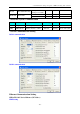
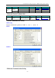
HMI Setting
Note:In the dual redundancy system, just set one of IP addresses in Network Device Setting
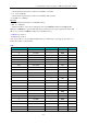
PLC Setting
Must set the PLC station in PLC program software.
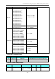
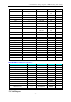
◎Supported Device
LM
Device Bit Address Word Address Format Notes
Discrete inputs and image Relay I0.0-2.7 ------ D.O
Discrete outputs and image Relay Q0.0-1.7 ------ D.O
Internal memory Relay M100.0-7816.7
------
DDDD.O
M0-99 are occupied
by system diagnosis.
Analog inputs ------ IW0 D
address must be an
even number;
IW,QW address
range to 30 by
adding a module
Analog outputs ------ QW0 D
Internal register ------ MW0-8190 DDDD
Internal register(double word)
------
MD0-8188 DDDD
Note: I,IW register read only
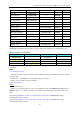
LK
Device
Bit Address
Word Address
Format
Notes
Outputs Relay
0X 1-65535
------
DDDDD
Inputs Relay 1X 1-65535 ------ DDDDD
Analog inputs ------ 3X 1-65535 DDDDD
Data Register ------ 4X 1-65335 DDDDD
Data Register(DWord) ------ 5X 1-65535 DDDDD
- 116 -