7 Burner Controls 785 LOK16... LGK16... Burner controls For gas, oil or dual-fuel forced draft burners of medium to high capacity For multistage or modulating burners in continuous operation With air pressure supervision for checked air damper control.
Use Burner controls type LOK16.../LGK16... feature a self-checking flame supervision circuit. The flame supervision circuit initiates the safety actions in the case of... : • ... premature or missing flame signal • ...
Warning notes To avoid injury to persons, damage to property or the environment, the following warning notes must be observed! Do not open, interfere with or modify the unit! All activities (mounting, installation and service work, etc.) must be performed by qualified staff Before making any wiring changes in the connection area, completely isolate the plant from mains supply (all-polar disconnection).
Installation notes Always run the high-voltage ignition cables separately while observing the greatest possible distance to the unit and to other cables Neutral conductors must not be interchanged Install switches, fuses, earthing, etc.
Commissioning notes For the connection of valves and other components, the diagram of by the burner manufacturer is provide.
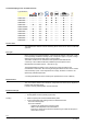
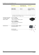
Certified with plug-in base and flame detector: Type reference LOK16.140... --- --- --- LOK16.250... --- --- --- LOK16.650... --- --- --- LGK16.122... --- --- LGK16.133A17 --- --- --- --- LGK16.133A27 --- --- LGK16.322... --- --- LGK16.333... --- --- LGK16.335... --- --- LGK16.622... --- --- LGK16.635...
Type summary The type references given below apply to the LOK16 without plug-in base and without flame detector. For ordering information for plug-in bases and other accessories, see Accessories. Switching times are given in the order of the startup sequence, valid for 50 Hz mains frequency. At 60 Hz, the times are about approx. 17% shorter. The type references apply to burner controls operating on AC 230 V, 50...60 Hz. * For burner controls operating on AC 100...110 V, 50...
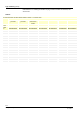
Type summary (cont’d) The type references given below apply to the LGK16 without plug-in base and without flame detector. For ordering information for plug-in bases and other accessories, see Accessories. LGK16... For flame supervision with flame detector QRA53.../QRA55... or ionization probe Preferred use: Flash-steam generators Flash-steam generators Also suited for direct-fired air heaters) Type LGK16.122A27* LGK16.133A27 LGK16.322A27* LGK16.333A27* LGK16.335A27* LGK16.622A27* LGK16.
Accessories (to be ordered separately) Oil burner controls, without plug-in base For AC 230 V* Control sequence and connection diagram like Preferred use LOK16.140A27* LAL2.14 Flash-steam generators LOK16.250A27* LAL2.25 Universal application LOK16.650A27 LAL2.65 Heavy-oil burners * Connection accessories for medium-capacity burner controls For burner controls operating on AC 100...110 V, 50...
Accessories (to be ordered separately) (cont‘d) Gas burner controls, without plug-in base For AC 230 V* Control sequence and connection diagram like Preferred use LGK16.122A27* LFL1.122 Flash-steam generators LGK16.133A27 LFL1.133 Flash-steam generators LGK16.322A27* LFL1.322 Also suited for direct-fired air heaters LGK16.333A27* LFL1.333 LGK16.335A27* LFL1.335 LGK16.622A27* LFL1.622 LGK16.635A27* LFL1.
Accessories (to be ordered separately) (cont‘d) Actuators Actuator SQN7 Refer to Data Sheet N7804 Actuator SQN3/SQN4 Refer to Data Sheet N7808 Actuator SQM40... / SQM41 Refer to Data Sheet N7817 Actuator SQM5... Refer to Data Sheet N7815 Others Flame detector current measuring device KF8832 Article no.: BPZ:KF8832 For detector current measurements with QRA53..., QRA55...
Technical data General unit data LOK16.../LGK16... Mains voltage Mains frequency Unit fuse, built-in Primary fuse (external) Weight Power consumption Perm. mounting position Degree of protection Safety class Perm. input current at terminal 1 Perm. current load of control terminals Required switching capacity of switching devices Between terminals 4 and 5, 4 and 12 Between terminals 4 and 14 AC 230 V -15% / +10% AC 100 V -15%...AC 110 V +10% 50...60 Hz ±6% T6,3H250V to DIN EN 60 127 Max.
Technical data (cont´d) Flame supervision LOK16... LGK16... RAR9... QRA5x.C... QRA5x.E... QRA5x.D... QRA5x.G... Ionization probe
Detector current measurement (cont´d)) LGK16 The measuring device must be connected between terminal 24 and the detector electrode (+pole to terminal 24). With ionization 24 DC 12...100 µA ION + A 7785v03/1008 Burner Burner control Terminals in the control panel Terminals in the burner compartment LGK16... base 1 2 22 23 15 1 Mains cable 3 x 1.5 mm 2 5 5 1 2 5 QRA5... 3 3 4 Shielding Max. 60 m A RAR9... ION 1 2 Single-wire coaxial cable (e.g.
Function Principle of self-supervision In contrast to conventional amplifiers, the signal delivered by the flame detector is handled dynamically and not statically. The flame detector signal is converted to a sequence of control pulses and then fed to the flame relay circuit. The latter is designed such that the flame relay can only be energized by a flame signal of the described form.
Startup program A Start When control thermostat or pressurestat closes, the burner control’s sequence switch starts running. At the same time, the fan motor connected to terminal 6 (only prepurging) receives power and, on completion of switch-on delay time, the fan motor or flue gas fan at terminal 7 (pre- and postpurging) also receives power. On completion of interval (t16), the control command to open the air damper is given via terminal 9.
Startup program (cont’d) Interrupted pilot burner with LGK16 (burners using a pilot burner) t3 t3‘ Short preignition time; followed by release of fuel for the pilot burner via terminal 17. TSA TSA‘ Note! (Only for LGK) For use in applications in dual-fuel burners or oil burners, the oil supply must be equipped with two shutoff valves connected in series. Observe the following: EN 298:2012, Section 7.101.3.3 Prepurge time for oil burner control systems and the corresponding application standards.
Control sequence in the event of fault and indication of lockout In case of any disturbance, the supply of fuel will immediately be interrupted. At the same time, the sequence switch stops and thus the lockout indicator also.
Control sequence in the event of fault and indication of lockout (cont´d) a Lockout indication a P a b´ P b´ b P 1 2 1 2 1 b LOK16.140... LOK16.250... LOK16.650... b LGK16.122... LGK16.133... LGK16.322... LGK16.333... LGK16.622... a a P b´ b P 2 1 1 2 b 7785p02/0296 LGK16.335... LGK16.635...
Connection diagrams (for circuitry variants, see Connection examples) LOK16... zm a t1 t11 t16 t7 t10 A 1 2 21 3 t4 t13 t5 1 t6 AS B C D A 13 12 14 TSA t3n t3 t12 t3´ P 4 5 6 7 15 16 17 18 19 1(3) SB H 20 9 11 10 8 RAR9...
Connection diagrams (for circuitry variants, see Connection examples) (cont’d) LGK16... z m a t16 t10 t7 A 1 2 21 2 t13 t5 t4 TSA t5 t9 B C D A 3 13 12 14 1 t6 AS TSA´ t4´ t3 t12 t3´ t1 t11 P 4 5 6 7 16 17 18 19 20 11 9 10 8 22 23 15 1 LR d1 SB 1(3) bv... W GP d2 2 5 SA R N N L N Si M1 AL LP M2 z a m + M M H EK2 v 3 4 1 BV1 Z BV2 ZBV BV1 7785a02e/0604 QRA5... 1) BV3 LK BV2 TSA´, t3´, t4´, only: LGK16.335 and LGK16.
Connection diagrams (for circuitry variants, see Connection examples) LGK16... SB 1 ION AS br1 b a ar1 I a 4 ar2 b XV a b QRA5...
Program sequence LGK16... A II III IV V VI VII VIII t1 C B t12 t6 Control output D at terminal: 12 a b t7 a b a b a b a b a b I t11 t3 7 t4 19 16 10 9 9 t16 11 20 a b a b TSA 8 t20 18 IX *t4´ *t3´ a b X t9 17 t5 *TSA´ XI XII XIII XIV XV a b a b a b t10 t13 12 a b 7 t8 7785d03e/0805 Lockout indication position P 1 2 * Times safety time (TSA´), long preignition time (t3´) and interval (t4´) are only programmed by burner controls LGK16.335... and LGK16.635... LOK16.
Program sequence (cont’d) Expanding flame burners (burners without a pilot burner), controlled and supervised by LOK16... or LGK16... Air damper in low-fire position during burner off times (min.). B A T C D R P t7 t6 t1 M1 M2 M ~ t3 Z TSA BV1 t4 LR R t5 100% M min. LK 0... BV2 t11 t12 FS 7785d01/0901 Interrupted pilot burners (burners with pilot burner), controlled and supervised by LGK16.335 or LGK16.635, for example. The other types of burner controls of the LGK16...
Connection examples 16 LGK16... 17 18 19 Doubling of safety time with expanding flame burners when using burner control LGK16.335... or LGK16.635... BV2 BV1 Z N By connecting terminals 17 and 18, the safety time is doubled and the preignition time reduced by 50%. Before using this circuit, it must be ensured that the longer safety time is in compliance with national standards and regulations etc. and with the construction of the burner plant! 7785a03/1295 19 18 LOK16...
Legend a AL AR AS B BR BV... bv... d... EK... ION FR FS GP H L... LK LP LR m M... NTC QRA... R RAR9... SA SB Si SM v V W z Z ZBV End switch for the OPEN position of the air damper Remote lockout warning device (alarm) Main relay (load relay) with «ar» contacts Unit fuse Wire link (on the burner control’s base) Note! In applications involving air heaters (WLE), or in the case of oil burners with a maximum throughput of > 30 kW/h, removing wire link B is not permitted.
Legend (cont’d) Lockout indication positions when there is no input signal (see Control sequence in the event of faults): ◄ ▲ ▼ No start Abortion of startup sequence Abortion of startup sequence ■ Lockout (fault in the flame supervision circuit) 1 2 P Lockout (no flame) Lockout (no flame) Lockout (no air pressure) Time table t1 TSA TSA´ t3 t3´ t3n t4 t4´ t5 t6 t7 t8 t9 t10 t11 t12 t13 t16 t20 max.
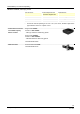
Dimensions Dimensions in mm 123 108,5 1,5 LOK16.../LGK16... Plug-in base AGM17/AGM17.1 7785m04/0305 27,5 7,5 103 37 27,5 103 28/28 Building Technologies Division 2017 Siemens AG Building Technologies Division, Berliner Ring 23, D-76437 Rastatt Subject to change! CC1N7785en 20.11.