
User Manual


4/28
Building Technologies Division CC1N7785en
20.11.2017
Installation notes
Always run the high-voltage ignition cables separately while observing the greatest
possible distance to the unit and to other cables
Neutral conductors must not be interchanged
Install switches, fuses, earthing, etc., in compliance with local regulations
Make certain that the maximum permissible current rating of the connection
terminals will not be exceeded
The insulation of internal wiring that is exposed to the mains voltage must
withstand the electrical stress occurring during correct use
Application notes
Note!
For use in applications in dual-fuel burners or oil burners, the oil supply must be
equipped with two shutoff valves connected in series.
Observe the following:
EN 298:2012, Section 7.101.3.3 Prepurge time for oil burner control systems and the
corresponding application standards.
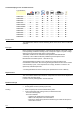
Electrical connection of flame detectors
It is important to achieve practically disturbance- and loss-free signal transmission:
Never run the detector cable together with other cables
– Line capacitance reduces the magnitude of the flame signal
– Use a separate cable
Observe the permissible detector cable lengths (see Technical data)
It is not permitted to connect 2 flame detectors QRA53.../QRA55... in parallel
When using the QRA53.../QRA55..., earthing of terminal 22 is mandatory
The ionization probe is not protected against electric shock hazard
Locate the ignition electrode and ionization probe such that the ignition spark
cannot arc over to the ionization probe (risk of electrical overloads) and that it
cannot adversely affect the supervision of ionization
Supervision with ionization probe and QRA53/QRA55 flame detector is possible
but, for safety reasons, both must not be active at the same time, with the
exception of the second safety time (t9). At the end of the second safety time, one
of the detected flames must extinguish, e.g. by shutting down the pilot gas valve
connected to terminal 17
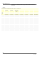
Commissioning notes
When commissioning the plant or when doing maintenance work, make the following
safety checks:
Safety check to be carried out Anticipated response
a) Burner startup with flame detector
darkened
Lockout at the end of safety time
b) Burner startup with simulated flame Lockout after no more than 40 seconds
c) Burner operation with simulated loss
of flame; for that purpose, darken the
flame detector in operation and leave
it in that state
LOK16... with wire link cut: Start
repetition followed by lockout at the end
of safety time
LGK16... and LOK16... with wire link
closed: Immediate lockout
d) Burner startup with response of air
pressure switch
Prevention of startup/lockout during
prepurge time
e) Burner operation with simulated air
pressure failure
Immediate lockout