
Basic Documentation
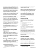
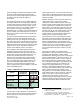

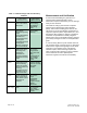
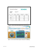
Table Of Contents

supplied separately. To simplify comparison, all the
values listed in Table 2 exclude the reheat coil.)
Figure 1. Typical Air Path in Terminal.
Table 2. Effect of Air Terminal on Environment.
Type of
Terminal
Pressure
Loss
Fan Power
(per 1000
cfm, 70%
efficiency)
Annual
Carbon
Dioxide
Emission
9
Venturi air
valve
0.6 in. WC
150 Pa
0.10 kW 720 kg
Venturi air
valve with
sound
attenuator
0.8 in. WC
200 Pa
.14 kW 960 kg
Low-
pressure
Venturi
0.3 in. WC
75 Pa
.052 kW 360 kg
Single-
blade
damper
< 0.1 in.
WC
< 25 Pa
.017 kW 120 kg
Page 6 of 14 Siemens Industry, Inc.
Document No. 149-488
Pressure drop is one important selection criterion.
Designers also weigh other characteristics, including
the amount of sound generated by the ventilation
system. In some cases, to achieve the desired
indoor environment, they add sound attenuators to
the system. This additional component adds another
pressure loss to the sum. Sound attenuators are
9. American Society of Heating, Refrigerating and Air-
Conditioning Engineers, Inc., BSR/ASHRAE//USGBC/IESNA
Standard 189P. Proposed Standard 189, "Standard for the
Design of High-Performance Green Buildings Except Low-
Rise Residential Buildings" (May 2007).
much more likely to be selected with Venturi valves
than with single-blade dampers.
Together these characteristics cause Green design
teams to see terminal selection as an important part
of low-pressure design.
Resetting Duct Pressure
While low-pressure design is important, any energy
engineer knows HVAC systems spend very little time
running at design conditions. The long periods of
operation at part-load really pile up the energy
consumption. Efficiency at the lower loads is the key
to energy conservation. The fan control system is a
great example.
For each component in the ventilation system, the
pressure loss discussed above depends on the
amount of air flowing through it. For fan sizing
calculations, designers consider the pressure loss at
design flow; the actual flow needed from the fan at
any other operating point is less. The conventional
approach to controlling a VAV fan is to select a
location in the duct system, install a sensor, and
hold the pressure fixed at that point. This design is
effective, but it uses more energy than necessary.
10
That’s because the fan ends up working harder to
push air through dampers that are partly closed.
The more efficient approach is to dynamically adjust
the pressure in response to the changing airflow.
ASHRAE’s energy efficiency standard
11
requires a
duct pressure reset that slows the fan down until at
least one of the flow control dampers is nearly all the
way open. This doesn’t affect the delivery of air; the
required flow rates are maintained; it just works
smarter. Duct pressure reset becomes a LEED
requirement too because compliance with ASHRAE
Standard 90 is prerequisite to a LEED-NC rating (EA
P2).
There are quite a few ways to implement a duct
pressure reset.
12
One of the most sophisticated
applies a model of the duct system in the HVAC
control panel, and runs the fan sizing calculations
dynamically to determine the pressure needed at
any moment. Other approaches poll the individual
flow controllers to determine if the dampers are all
the way open.
10. ASHRAE, 2007 ASHRAE Handbook–HVAC Applications:
46.7.
11. ASHRAE, Standard 90.1-2007, "Energy Standard for
Buildings Except Low-Rise Residential Buildings".
12. 2007 ASHRAE Handbook–HVAC Applications: 46.7.