
Application

Sequence of Operation
Damper Position on Return from Power Failure
27
Siemens Industry, Inc.
Application Note, Application 6759
140-1335
2015-07-07
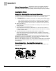
Network Annunciation
If the LCM is connected to a field panel, alarms can be reported using the workstation
software, or by using a printer that is set up in a building manager’s office to receive
alarms. Points in the controller must be entered in the field panel’s point database
(referred to as unbundling) and defined as alarmable. For example, if the room
pressurization alarm (VOL DIF ALM) is unbundled in a field panel and a pressurization
alarm is triggered, an alarm will be annunciated across the network.
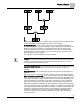
Damper Position on Return from Power Failure
On a return from power failure, the damper-command DOs (DOs1 through 4) remain
OFF for 5 seconds prior to resuming control. Because of this it is recommended that
the Supply Damper Motor Setup be set to Enabled (normally closed) for rooms where
negative or neutral pressurization is required and Enabled and Reversed (normally
open, where the actuator is retracted) for positively pressurized rooms. Likewise, it is
recommended that the General Exhaust Damper Motor Setup be set to Enabled and
Reversed for rooms where negative or neutral pressurization is required and Enabled
for positively pressurized rooms. The default for the Motor direction is direct (not
reversed).
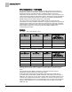
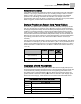
Use the values in the followin table to determine the value for MTR SETUP. The values
are additive. For example, if you want to have Motor 1 (DOs 1 and 2) enabled, Motor 2
(DOs 3 and 4) enabled and reversed, you would set MTR SETUP equal to 13. (This is
because the Motor 1 enable value is 1, the Motor 2 enabled and reversed value is 12,
1+12=13.)
Not Used
Enabled
Enabled
and
Reversed
Motor 1 (supply damper)
(DO 1 and DO 2)
0
1
3
Motor 2 (exhaust damper)
(DO 3 and DO 4)
0
4
12
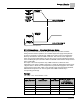
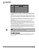
Operation of AVS FAILMODE
AVS FAILMODE is an enumerated point that describes how the supply Damper and
the general exhaust Damper will respond if one or both Air Velocity Sensors (AVS) fail.
It can handle both positively pressurized rooms and negatively pressurized rooms.
The default value of AVS FAILMODE is
0. This default causes both the supply and
general exhaust to hold their current position when an AVS fails. Open Supply, Open
Exhaust and Close Supply, Close Exhaust are not defined AVS FAILMODE states.
AVS Failure and AVS FAILMODE Table Values.
AVS FAILMODE
0
(default)
Hold Supply, Hold General Exhaust
1
Hold Supply, Open General Exhaust
2
Hold Supply, Close General Exhaust
3
Open Supply, Hold General Exhaust