Fume Hood Sash Open Area Module (SOAM) Application 2954: Bench Style – 2 to 10 Horizontal Sashes Configuration Start-up Procedures Building Technologies A6V10801613 07.06.
Table of Contents Before You Begin ..................................................................................................3 Verifying Power .........................................................................................................3 Installing USB Driver .................................................................................................3 Verifying Slave Mode Application ..............................................................................
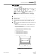
Before You Begin Verifying Power Before You Begin WARNING A fume hood is a safety device. Anyone attempting to start up a Fume Hood Controller and its related equipment must have completed Operations Training. WARNING DO NOT connect to the USB port of the SOAM while the fume hood is in operation. At the job site, locate the major control system and the mechanical and electrical drawings. This should include any components working in conjunction with the Sash Open Area Module (SOAM).
Before You Begin Setting Controller Address Setting Controller Address 1. If using the sensor bus to communicate the face area: Verify CTLR ADDRESS is correct (default is 51 and does not need to be changed). Setting the Application 1. Select the desired application.
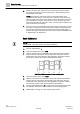
Before You Begin Fume Hood Specific Sash Setup and Calibration Sash Setup 2954 1. Set REPORT to OVERVIEW. NOTE: Numbers on the sashes show how the sash is wired. After the physical sashes are calibrated, the position of the sashes will display in POS SASH 1, POS SASH 2, and so on. 2. Determine the number of horizontal sash panels. Set HZ PANEL CNT to this value. 3. Measure the length of the horizontal opening in inches (cm). Set TRACK WIDTH to this value. 4.
Before You Begin Fume Hood Specific Sash Setup and Calibration 6. Measure the fixed area of the fume hood in square feet (square meters). Any fume hood leakage must be accounted for in this measurement. Set FIXED AREA to this value. NOTE:The fixed area of the fume hood is an area that remains open regardless of sash position or movement. For example, most fume hoods have an intake gap under the lower airfoil and above the cabinet of the fume hood (typically a 1 inch gap).
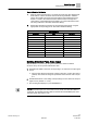
Before You Begin Setting External Face Area Input Sash Calibration Verification 1. Slide the horizontal sash panel 1 to the left and verify the value displayed at POS SASH 1 is at the minimum that was set during calibration. Slide the sash to the middle of its range and verify that the value displayed at POS SASH 1 is equal to the measured value. Slide the sash to the right and verify that the value displayed at POS SASH 1 is at the maximum that was set during calibration. See Table Sash/Point Wiring. 2.
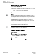
Before You Begin Setting Face Area Output Range Setting Face Area Output Range 1. Set REPORT to FACE AREA OUT. 2. Set MAX FACE A to the maximum expected face area for the fume hood, plus approximately 10%. Example: If the maximum face area is 9 sq ft, set it to 10. FACE A OUT is now active and a proportional 1 to 10V signal can be read on AO. 1V equals 0 sq ft and 10V = MAX FACE A. 3. Set AO DEADBAND to the desired value. NOTE: AO DEADBAND can be set from 0 to 100% in 0.4% increments.
Issued by Siemens Industry, Inc. Building Technologies Division 1000 Deerfield Pkwy Buffalo Grove IL 60089 +1 847-215-1000 © Siemens Industry, Inc., 2016 Technical specifications and availability subject to change without notice. Document ID: A6V10801613 Edition: 07.06.