
Data Sheet for Product

Siemens Industry, Inc.
Page 7 of 8
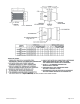
Unit Size 214
Performance Notes:
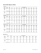
1. Tabulated values are in MBH (thousand of Btu per hour).
2. Tables are based on temperature difference of 110°F (180°F entering water temperature and 70°F entering air temperature). For other temperature
differences, multiply MBH values by factors as listed above.
3. Minimum air and water flow values are based on ASHRAE recommendations for coil selections. For selections below these tabulated air or water values,
please consult your local representative.
4. Do not select coils for a leaving air temperature above 120°F.
5. HD (Head) loss is in ft. of water.
6. Through the coils delta P, is the pressure drop in in. of water across the coil.
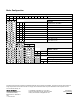
7. Air temperature rise = ATR, ATR (F) = 927 x MBH/cfm
8. Water temperature drop = WTD, WTD (F) = 2.04 x MBH/gpm
9. Values in tables are listed for 0 ft of altitude and no glycol in the system.
10. For information outside the ranges used in the table, consult your representative.
11. Heating coils used in the unit have performance rated and certified in accordance with the current edition of the AHRI Standard 410.
12. Connections: Single Circuit – 1/2 in. OD male solder; Multi Circuit – 7/8 in. OD males solder.
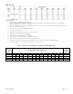
Table 1. Capacity Correction Data for 1 and 2-Row Hot Water Reheat Coils
Entering
Air Temp
(°F)
Entering Water Temperature (°F)
Entering
Air Temp
(°F)
90
100
110
120
130
140
150
160
170
180
190
200
210
45
0.36
0.44
0.52
0.60
0.68
0.76
0.84
0.92
1.00
1.08
1.16
1.24
1.32
45
50
0.32
0.40
0.48
0.56
0.64
0.72
0.80
0.88
0.96
1.04
1.12
1.20
1.28
50
55
0.28
0.36
0.44
0.52
0.60
0.68
0.76
0.84
0.92
1.00
1.08
1.16
1.24
55
60
0.24
0.32
0.40
0.48
0.56
0.64
0.72
0.80
0.88
0.96
1.04
1.12
1.20
60