Universal Sash Fume Hood Controller Owner’s Manual 125-5032 Rev.
Rev. AA, September 2007 NOTICE The information contained within this document is subject to change without notice and should not be construed as a commitment by Siemens Building Technologies, Inc. Siemens Building Technologies, Inc. assumes no responsibility for any errors that may appear in this document. All software described in this document is furnished under a license and may be used or copied only in accordance with the terms of such license.
Table of Contents How To Use This Manual ............................................................................................. VIII Manual Organization ................................................................................................. VIII Manual Conventions.................................................................................................. VIII Manual Symbols ........................................................................................................
Applications .................................................................................................................. 13 Basic Operation ............................................................................................................ 13 Average Face Velocity Control.................................................................................. 13 Minimum and Maximum Flow Rates ......................................................................... 13 Display Filters ..............
Controller LEDs ......................................................................................................... 33 Glossary ........................................................................................................................ 34 Index .............................................................................................................................. 38 Siemens Building Techologies, Inc.
How To Use This Manual This section covers manual organization, conventions, and symbols used in the manual, and other information that will help you understand and use a Laboratory Room Controller — Electronic Output. Manual Organization This manual contains the following sections: • Chapter 1 Product Overview describes the hardware components and the accessories that are used with the controller. • Chapter 2 Applications describes the control applications available in the controller.
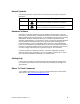
Manual Symbols The following table lists symbols that are used to draw your attention to important information. Notation Symbol Meaning CAUTION: Indicates that equipment damage or loss of data may occur if the user does not follow a procedure as specified. WARNING: Indicates that personal injury or loss of life may occur to the user if a procedure is not performed as specified. Datamate Software Datamate is a customer software tool for all controller communications.
1 Product Overview Introduction The Fume Hood Controller is a multi-application equipment controller designed to provide Direct Digital Control (DDC) for various types of Variable Air Volume (VAV) fume hoods. The controller consists of a controller board and a controller enclosure.The controller board (Figure 1) is the central computing/controlling component of the system.
Fume Hood Controller Owner's Manual Table 1. Fume Hood Controller – Electronic Output Applications. Application Description 941 Universal Sash (Walk-in) with Damper 942 Universal Sash Walk-in with Venturi Air Valve Ordering Notes Fume Hood Controller – Electronic Output with Damper (941) 546-00705 Fume Hood Controller – Electronic Output with Venturi Air Valve (942) 546-00705 Figure 1. Fume Hood Controller Board . 2 Siemens Building Technologies, Inc.
Product Overview Hardware Inputs Analog • Differential pressure transmitter • Horizontal sash sensor(s) • Vertical sash sensor(s) • Operator Display Panel (ODP) • ATTN.UNATTN (through DI 1) • OCC.UNOCC (through DI 1) Digital Hardware Outputs Analog • AO-E module (analog control) • Operator Display Panel (ODP) • AO2 (flow signal) • FLN communications trunk • Sash Alert Digital Power Wiring The controller is powered by 24 Vac.
Fume Hood Controller Owner's Manual FLN TRUNK + - S TEC0470R1 LAB00140R1 (SHIELD) 24V COMMON 24V HOT GROUND Figure 2. Power Wiring. (SHIELD) (-) (+) (-) (+) Figure 3. Communication Wiring. Controller LED Indicators The controller has six Light Emitting Diode (LED) indicators. See Table 2. Table 2. Controller LEDs. LED Type Label (if present)* Indication DO LED 1 - LED 3 Transmit TX Indicates, when flashing, that the controller is transmitting information to the field panel.
Product Overview Pressing the Emergency Purge button a second time reverts the Fume Hood Controller to normal operation for the current conditions. Auxiliary Button – The Auxiliary buttons are not used currently. For more information on the ODP, see the Fume Hood Controller Operator Display Panel User's Card (125-1976). Figure 4. Operator Display Panel. UniTrak™ Sash Sensors UniTrak™ sash sensor strips are used in conjunction with the sash sensor actuator to measure the position of the fume hood sash.
Fume Hood Controller Owner's Manual ACTUATOR BLOCK CONNECTOR SENSOR CONNECTOR DECORATIVE COVER PLATE CONNECTOR REMEMBER TO CLOSE THE SASH SENSOR SASH SHIELD LINKAGE ACTUATOR BLOCK MOUNTING PLATE REMEMBER TO CLOSE THE SASH FUM0376R1 HORIZONTAL SASH LINKAGE UNITRAK SENSOR VERTICAL SASH LINKAGE Figure 5. UniTrak Assembly Kit. CONNECTOR ACTUATOR STOP FUM0374R1 SENSOR SASH SHIELD Figure 6. Vertical Sash Sensor with Shield. 6 Siemens Building Technologies, Inc.
Product Overview FUM0375R1 ACTUATOR BLOCK CONNECTOR Figure 7. Horizontal Sash Sensor with Shield. Sash Sensor Actuator UniTrak™ sensors have built-in sensor strip actuators: the horizontal UniTrak™ has two and the vertical UniTrak™ has one. The actuators (see Figure 8) ride along the sensor strip to vary the resistance reading to the Fume Hood Controller. The resistance reading is then used to determine the sash positions. Figure 8. Fume Hood Controller Sash Sensor Actuator.
Fume Hood Controller Owner's Manual Figure 9. Fume Hood Exhaust Terminal. 8 Siemens Building Technologies, Inc.
Product Overview Venturi Air Valves The Venturi Air Valve is a pre-packaged, easy to install airflow measurement and control station. See Figure 10. This assembly combines the orifice plate flow sensor, differential pressure transmitter, Analog Electronic actuator and a Venturi Air Valve. FUM0400R1 This arrangement provides fast acting, stable, and precise VAV fume hood exhaust airflow control. Figure 10. Single-Body Venturi Air Valve.
Fume Hood Controller Owner's Manual Electronic Damper Actuator Assembly The electronic damper actuator assembly consists of two parts, the electronic actuator and the interface board. The actuator is connected to a damper or Venturi Air Valve in the fume hood exhaust duct. The electronic actuator assembly is used because of its small size and quick response time.
Product Overview Figure 14. Pneumatic Damper Actuator. Analog Output-Pneumatic (AO-P) Module The Analog Output-Pneumatic (AO-P) Module is an electric-to-pneumatic interface between the Fume Hood Controller and the damper actuator. The AO-P Module translates electrical signals from the Fume Hood Controller into pneumatic signals that command the damper actuator. The AO-P Module consists of two industrial grade air valves that supply or bleed air to the damper actuator by using a pulse modulation technique.
Fume Hood Controller Owner's Manual Differential Pressure Transmitter The differential pressure transmitter is used to send a signal that represents the velocity of air in the duct to the controller. The differential pressure transmitter receives the velocity pressure signal from the airflow sensor (orifice plate). The transmitter is a dead-end device which prevents the exhausted fume hood air from flowing through the transmitter or the sensor.
2 Applications Basic Operation The Fume Hood Controller provides Direct Digital Control (DDC) technology for controlling fume hood face velocities in a manifolded fume hood exhaust system. Average Face Velocity Control The Fume Hood Controller maintains the average face velocity by calculating the open area of the fume hood sash using inputs from the sash sensors and other measured constants. The controller then determines the exhaust airflow volume to reach the face velocity setpoint.
Fume Hood Controller Owner's Manual The Fume Hood Controller maintains a constant face velocity until the maximum flow condition occurs. At that point, the controller controls to a constant exhaust volume. In the maximum flow mode, the face velocity drops below the desired setpoint as the open sash area increases toward the fully open position. This may cause an alarm condition to occur. Display Filters If enabled, the average face velocity is displayed at the ODP.
Applications Warning Operation The Fume Hood Controller announces warning conditions at the ODP. The ODP indicates a warning condition by illuminating the yellow LED. If the fume hood is operating in the face velocity mode and the face velocity exceeds the high or low warning limit for a period greater than the delay timer a warning condition occurs.
Fume Hood Controller Owner's Manual The delay timer is adjustable and should be selected with safety in mind. Laboratory safety procedures will not be effective if there are numerous nuisance alarms. The delay timer should be set at a sufficiently large interval to prevent nuisance alarms. However, if the delay timer interval is excessively large, there is a risk of having a laboratory worker standing in front of an ineffective fume hood for a prolonged period.
Applications • The horn sounds. • EMERGENCY PURGE and EEE display. The fume hood operator may silence the horn by pressing the Horn Silence button on the ODP without affecting the Emergency Purge sequence. For more information on ODP messages, see the Fume Hood Controller Operator Display Panel User's Card (125-1976). In addition to the ODP indicators, the emergency alarm point will toggle to ON and will remain ON until the sequence is canceled.
Fume Hood Controller Owner's Manual If a sequence initially employing maximum purge with a switch to controlled purge is desired, set the emergency setpoint as described for the controlled purge. Select a value for the emergency timer to tell the system how long to leave the damper open before switching to controlled purge. Base this on the types of accidents anticipated, the reason you require a maximum purge, and the reason you want to switch it down to a controlled purge.
Applications Pneumatic Damper Actuator If the damper actuator fails due to a leak, then the damper will go to the full open position. Alarms will be displayed on the ODP indicating unsafe operating conditions. Venturi Air Valve If the Venturi Air Valve fails, alarms will be displayed on the ODP indicating unsafe operating conditions. AO-P Module If the AO-P module fails, alarms will be displayed on the ODP indicating unsafe operating conditions.
Fume Hood Controller Owner's Manual SEG COUNT = 1 SEG SASH CNT = 1 SEG COUNT = 1 SEG SASH CNT = 2 Figure 16. Multi-Vertical Sash Configurations with Wiring and Point Information. HZ PANEL CNT = 2 HZ PANEL CNT = 4 Figure 17. Horizontal Sash Configurations with Wiring and Point Information. 20 Siemens Building Technologies, Inc.
Applications HZ PANEL CNT = 2 HZ PANEL CNT = 4 Figure 18. Combination Sash Configurations with Wiring and Point Information. TRACK TRACK WIDTH PANEL TOP FRAME WIDTH PANEL WIDTH WIDTH 3 2 V SASH 1 PANEL HEIGHT HEIGHT 2 V SASH 1 PANEL HEIGHT HEIGHT 1 3 4 5 1 TRACK HEIGHT V SASH 6 HEIGHT TRACK HEIGHT V SASH 6 PANEL HEIGHT HEIGHT 6 SASH WIDTH FUM0384R1 FUM0385R1 TOP FRAME 6 SASH WIDTH Figure 19. Walk-in Combination Sash Configurations with Wiring and Point Information.
Fume Hood Controller Owner's Manual Application 941: Universal Sash with Damper Figure 20. Application 941 Control Drawing. 22 Siemens Building Technologies, Inc.
Applications Airflow Control The PID loop controls the damper based on the values of the exhaust flow and the flow setpoint. The loop output controls the supply and exhaust through a time modulation scheme. The control loopout ranges from -100 to 100%. • -100% is the maximum supply that closes the damper at full speed. • 0% holds the damper at its current position. • 100% is the maximum exhaust that opens the damper at full speed.
Fume Hood Controller Owner's Manual Application 942: Universal Sash with Venturi Air Valve Figure 21. Application 942 Control Drawing. 24 Siemens Building Technologies, Inc.
Applications Airflow Control There are two parts to the flow control; they operate in succession and never at the same time. If a change occurs in the face area, feed forward control is used; during steady state conditions the PID control loop is used. Feed Forward Control - When a change in the face area is detected, Feed forward control is used.
Fume Hood Controller Owner’s Manual 3 Point Database Chapter 3 presents a description of the Fume Hood Controller point database including point descriptors, point addresses, and a listing of applications in which each point is found. Address Descriptor Application 01 CTLR ADDRESS 941, 942 Identifies the controller on the FLN trunk. Valid values: 0 through 98. 02 APPLICATION 941, 942 The identification number of the Application running in the controller.
Point Database 11 HI WARN LMT 941, 942 The value above FVEL STPT, in percent, at which the yellow LED is illuminated on the ODP. Valid values: 100 through 255%. 12 LOW WARN LMT 941, 942 The value below FVEL STPT, in percent, at which the yellow LED is illuminated on the ODP. Valid values: 0 through 100%. 13 LOW ALM LMT 941, 942 The value below FLOW STPT, in percent, at which the red LED and audible alarm activates on the ODP. This point is the setpoint for LOW ALM. Valid values: 0 through 100%.
Fume Hood Controller Owner’s Manual 28 27 UN ALRT AREA 941, 942 The open area in square feet (SQM) at which the Sash Alert feature will start beeping the horn during unattended operation. 28 UNATTN TIME 941, 942 This point delays the sash alert function, a user defined number of seconds, when the controller is in UNATTN mode. 30 AO2 RANGE 941, 942 Scaling for the Analog Output (AO2) point.
Point Database 47 AO2 FLOW SIG 941, 942 Analog output 2 signal is used to indicate the exhaust flow setpoint. The output is 1 to 10 Vdc, which corresponds to 0 to A02 RANGE (Point 30). 48 DI1 941, 942 Spare digital input for dry contact connection. 49 VERT SASH1 941, 942 Current position, in inches (cm), of the vertical sash wired as sash 1 at the controller board. If not physically wired to the controller, this point may appear as 'failed'.
Fume Hood Controller Owner’s Manual 30 68 CTRL LOOPOUT 941, 942 Control output of the flow loop. Range: -100% to 100%. 69 SASH OP ALRT 941, 942 This point turns ON when the face area is larger than UN ALRT AREA or AT ALRT AREA depending on the state of ATTN.UNATTN 70 FACE AREA 941, 942 The open area, in square feet (SQM), of the fume hood face, which includes the fixed area and accounts for the bypass area.
Point Database 91 BLANK DSPLY 941, 942 When set to YES, the face velocity is not displayed at the ODP. 92 ATTN.UNATTN 941, 942 ATTN or UNATTN point controls the mode of operation for the sash alert function. 93 ENG UNITS 941, 942 Toggles the display of the ODP from feet per minute to meters per second. Toggling this point does not change the displayed value at the portable operators terminal. 94 LAMP TEST 941, 942 Turns on all lights, prompts, and the audible alarm at the ODP.
4 Troubleshooting This chapter describes corrective measures you can take should you encounter a problem when using the Fume Hood Controller. For issues not covered in this section, contact your local Siemens Building Technologies, Inc. representative. You are not required to do any controller troubleshooting. Contact your local Siemens Building Technologies, Inc. representative if a problem occurs or you have any questions about the controller.
Troubleshooting Safety Features The controller board stores the controller's address, applications, and point values. In the event of a power failure or a reset, these values are retrieved from the controller’s permanent memory and are used by the controller unless overridden by a field panel. Controller LEDs To determine if the controller is powered up and working, verify that the Basic Sanity Test (BST) Light Emitting Diode (LED) is flashing ON/OFF once per second.
Glossary The glossary contains terms and acronyms that are used in this manual. For definitions of point database descriptors, refer to Chapter 3 - Point Database, in this manual. For definitions of commonly used terms as well as acronyms and abbreviations associated with the APOGEE Automation System, see the Technical Glossary of Building Controls Terminology and Acronyms, (125-2185). This book is available from your local Siemens Building Technologies, Inc. representative. AI Analog Input.
Glossary English units The foot-pound-second system of units for weights and measurements. equipment controller A FLN device which provides additional point capacity to a field panel or provides DDC to individual room or mechanical equipment control. The FHC is a specialized equipment controller. field panel A device containing a microprocessor for centralized control of system components and equipment controllers.
Fume Hood Controller Owner's Manual ON text Text indicating the energized state of a digital point (for example, ON, OPEN, YES). override switch Button on room temperature sensor which can be pressed by an occupant to change the status of a room from night mode to day mode for a predetermined time. PID Proportional, Integral, Derivative.
Glossary Terminal Equipment Controller Siemens Building Technologies, Inc. product family of equipment controllers (one is the Unit Conditioner Controller – Electronic Output) that house the applications software used to control terminal units, such as heat pumps, VAV terminal boxes, fan coil units, unit ventilators, etc. UniTrak™ Resistive strips on fume hood which, in conjunction with sash sensor actuator, senses the position of the fume hood sash. UNOCC mode UNOCCupied mode.
Index A D AI see analog input airflow sensor ................................................... 12 analog input ........................................................ 2 analog output ..................................................... 2 AO ........................................... see analog output AO-P module .................................................... 11 application 907 control drawing ............................................. 21 application 933 airflow control .....................
Glossary H hardware ......................................................1–12 autozero module ........................................... 25 LEDs ............................................................... 4 power wiring ............................................... 3, 4 hardware inputs.................................................. 3 analog ............................................................. 3 digital .............................................................. 3 hardware outputs ...