
Operating Instructions

Point Database
Siemens Building Technologies, Inc. 27
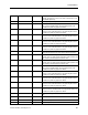
11 HI WARN LMT 941, 942 The value above FVEL STPT, in percent, at which the yellow
LED is illuminated on the ODP. Valid values: 100 through
255%.
12 LOW WARN LMT 941, 942 The value below FVEL STPT, in percent, at which the yellow
LED is illuminated on the ODP. Valid values: 0 through 100%.
13 LOW ALM LMT 941, 942
The value below FLOW STPT, in percent, at which the
red LED and audible alarm activates on the ODP. This
point is the setpoint for LOW ALM. Valid values: 0
through 100%
.
14 EMER TIMER 941, 942 When EMER ALM is set to ON, the time set for EMER TIMER
is used as the length of time the EXH FLOW is commanded to
full flow (the damper is full open). After the time in EMER
TIMER times out, the EXH FLOW is controlled to the value set
in EMER STPT. Valid values: 0 through 32, 767 seconds.
15 EMER STPT 941, 942 A value of the preset FVEL STPT, in percent, that the
controller uses as the setpoint when EMER ALM is ON.
16 LOW WARN 941, 942 This point displays an ON or OFF status. When the face
velocity goes below the value specified at LOW WARN LMT
for the time specified in ALARM TIME, the point goes into a
warning state (ON); the yellow LED is illuminated at the ODP.
17 HIGH WARN 941, 942 This point displays an ON or OFF status. When the face
velocity goes above the value specified at HI WARN LMT for
the time specified in ALARM TIME, the point goes into a
warning state (ON), the yellow LED is illuminated at the ODP.
18 FLOW MAX 941, 942 Maximum flow setpoint allowed. FLOW MAX will override the
FVEL STPT if the calculated FLOW STPT is greater than
FLOW MAX.
19 ALM AKNLG 941, 942 This point displays an ON or OFF status that indicates the
Horn Silence button has been pressed at the ODP to
acknowledge an alarm condition. The point will reset when the
alarm condition clears or another alarm is initiated.
20 STARTUP MODE 941, 942 Toggles the ODP from normal operation to OFF mode. In OFF
mode, the alarms do not sound, the ODP displays OFF and
the RED LED is on.
21 TABLE PARAM1 941, 942 This point modifies internal parameters as selected by point
31.
22 DISPLAY RES 941, 942 A change of value (COV) limit for the face velocity displayed at
the ODP. The display does not update unless the change in
face velocity exceeds this value.
23 CAL VENTURI 942 YES or NO point used to calibrate AO1 ACT SIG to the
associated flow rate.
24 AO2 DEADBAND 941, 942 When EXH FLOW and FLOW STPT are different by more than
the AO2 DEADBAND, the AO2 FLOW SIG changes from
setpoint to actual flow.
25 VENTURI STAT 942 PASS OR FAIL point used to indicate if the last calibration
attempt passed.
26 CAL MODULE 942 YES or NO point used to indicate if an AZM module is
attached to AZM DO2.