BACnet Programmable Fume Hood Controller 2-Position Constant Volume with Damper Application 6740 Application Note Building Technologies 140-1341 2015-11-09 Restricted
Table of Contents Overview ............................................................................................................................. 4 BACnet .............................................................................................................................. 5 Auto Discovery ..................................................................................................................... 5 Auto Addressing ......................................................................
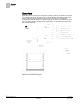
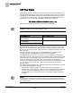
Overview BACnet Overview Application 6740 is designed for use with a constant volume or two position fume hood in a manifold fume hood exhaust system. In this application, two position fume hoods have an individual exhaust damper connected to a central fan. The application modulates the exhaust damper to maintain a high or low flow set point based on inputs from the ODP (Operators Display Panel), digital Input, an exhaust air flow sensor and the controller setpoints. Application 6740 Control Diagram.
Overview BACnet BACnet The controller communicates using BACnet MS/TP protocol for open communications on BACnet MS/TP networks.
Overview Hardware Inputs Hardware Inputs Analog Air velocity sensor(s) – (2nd sensor available for field use) (Optional) Differential pressure transmitter/Linear Flow input (Vortex Shedder) Digital Operator Display Panel (ODP) (Optional) High/Low select (through DI 2) (Optional) Startup Mode (through DI 4) (Optional) Remote Emergency Purge (through DI 6) Hardware Outputs Analog Operator Display Panel (ODP) AO2 (flow signal, 1 to 10 Vdc) Digital Autozero Solenoid in Offboard
Sequence of Operation AVS Calibration Sequence of Operation The following paragraphs present the sequence of operation for Fume Hood Controller Application 6740, 2-Position Constant Volume Controller with Damper. The Fume Hood Controller can operate at two different setpoints, described as HI flow and LOW flow setpoints. The controller can be set to an OFF mode. In this mode the damper is closed and the controller enters into a standby mode of operation.
Sequence of Operation AO2 Flow Signal AO2 Flow Signal An analog signal of the exhaust flow is available at AO2 of the controller board and is displayed at EXH SIG AO2. To get an output from EXH SIG AO2, you must command AO2 RANGE to the maximum expected flow for the fume hood. Then AO2 is scaled such that 1 Vdc is equal to 0 cfm, and 10 Vdc is equal to AO2 RANGE. If the output drops below 1 Vdc, this indicates a GENERAL FAILURE or loss of power.
Sequence of Operation Control Loop DISPLAY RES is the COV limit for exhaust volume readings. NOTE: If you set DISPLAY RES to zero, the ODP continuously displays the value of EXH FLOW. Resetting DISPLAY RES to a value other than zero displays the EXH FLOW incrementally. The factory default is 5, cfm values displayed will be in increments of 5 (for example, 80, 85, 90, 95, 100, etc.). If the actual filtered cfm is 84, 85 will be displayed.
Sequence of Operation Alarm Limits Warning and Alarm Schedule. Alarm Limits The Fume Hood Controller contains high and low flow alarm limits, HI ALM LMT and LOW ALM LMT, respectively. The alarm limits are defined as a percentage of the controller setpoint; therefore, the alarm limits apply to EXH STPT during normal control. For either of the alarms to become active, the alarm condition must be maintained for the time specified in ALARM TIME.
Sequence of Operation Emergency Mode Emergency Mode The emergency mode operation overrides any other control mode in the Fume Hood Controller. When the Emergency Purge button on the ODP is pressed, the following sequence of events occurs. 1. EMER ALM turns ON at BACnet priority level 1, the horn sounds, and the red LED on the ODP illuminates. The ODP displays “EMERGENCY” mode and indicates to close the hood. 2.
Sequence of Operation Fail Mode The modes are described as an enumerated point: STARTUP MODE Mode Description 0 Normal 2 Non-functional Decommission, closed The controller is fully functional, except the flow setpoint is set to 0, alarming is limited and the ODP displays “Out of service” and “OFF”. If the sash is opened, nothing changes. 3 (default) Non-functional Startup The controller is fully functional, except alarming does not work and the ODP displays “Controller – Startup” and “OFF”.
Sequence of Operation Wiring Diagram Wiring Diagram Offboard Air Module Wiring. CAUTION The FHC-OAVS has two terminal blocks with terminations numbered identically (terminations 1 through 16). DO NOT mix these up with each other. If the FHC-OAVS is not connected as shown, it is not resistant to electrical surges. It is also susceptible to interference from other equipment. CAUTION A separate power supply is required if a 4-20 mA sensor is used.
Sequence of Operation Wiring Diagram NOTE: If the voltage/current switch is set to current and a 4 to 20 mA sensor is connected to an AI, then special wiring requirements must be followed. NOTE: The controller’s DOs control 24 Vac loads only. The maximum rating is 12 VA for each DO.
Sequence of Operation Wiring Diagram Application 6740 Wiring Diagram. 15 Siemens Industry, Inc.
Point Database Application 6740 Point Database Application 6740 Object Type Object Instance (Point Number) a) Object Name (Descriptor) Factory Default (SI Units) c) Eng Units (SI Units) c) Range Active Text Inactive Text AO 1 CTLR ADDRESS 99 -- 0-255 -- -- AO 2 APPLICATION 6700 -- 0-32767 -- -- BO {05} LOW ALM OFF -- Binary ON OFF BO {06} HIGH ALM OFF -- Binary ON OFF BO {07} EMER ALM OFF -- Binary ON OFF BO {08} GEN FAILURE OFF -- Binary ON OFF AO {
Point Database Application 6740 Object Type Object Instance (Point Number) a) Object Name (Descriptor) Factory Default (SI Units) c) Eng Units (SI Units) c) Range Active Text Inactive Text BO {42} RETC DO2 RETC -- Binary HOLD RETC BO {43} DO 3 OFF -- Binary ON OFF BO {44} DO 4 OFF -- Binary ON OFF BO {45} HI.
Point Database Application 6740 Object Type Object Instance (Point Number) a) Object Name (Descriptor) Factory Default (SI Units) c) Eng Units (SI Units) c) Range Active Text Inactive Text BO {110} ENG UNITS ENG -- Binary SI ENG AO {121} HI LIMIT 1 -- 0-2.55 -- -- AO {122} LO LIMIT 1 -- 0-2.55 -- -- BO {123} EMER DI6 OFF -- Binary ON OFF BO {125} ODP DISPLAY MODE -- Binary CFM MODE AO {126} AVE EXH VOL 0 (0.
Issued by Siemens Industry, Inc. Building Technologies Division 1000 Deerfield Pkwy Buffalo Grove IL 60089 Tel. +1 847-215-1000 Document ID 140-1341 Edition 2015-11-09 © Siemens Industry, Inc., 2015 Technical specifications and availability subject to change without notice.