
Basic Documentation
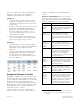
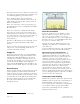

Table Of Contents
- Hospital Pharmacy–USP Compounding Standards
- Environmental Requirements for USP 795 & 797 Compliance
- Current USP Guidelines
- Center for Medicare and Medicaid Services (CMS) Compliance Date
- USP <795> Facility Requirements
- USP <797> Facility Requirements
- Equipment (Primary Controls)
- Design Requirements for CSP Pharmacies
- Building Exhaust Design Considerations
- Cleanroom Design Considerations
- HVAC Design Considerations
- Certification and Recertification
- Monitoring Controlled Storage Areas

Siemens Industry, Inc. Page 3 of 8
Document No. 149-224
Failure of Cabinet – The impact that a cabinet
failure will have on the room environment must be
considered during the design process. For example,
consider a system with the following cabinets:
Negative pressure barrier isolators, Class II BSC
Type B1, and Class II BSC Type B2. If the building
exhaust or cabinet exhaust fails, the cabinet will
become pressurized, causing airflow from the work
area to flow back into the room. Therefore, these
cabinets should have their exhaust ducted to the
outside.
Continuous Monitoring – Typically, cabinet
manufacturers provide a magnehelic gauge to
provide visual confirmation of cabinet operation.
Failure of the building exhaust system will not be
apparent to the user because the cabinet supply
blower will continue to operate. Therefore, a
pressure-independent monitor should be installed to
sound an audible alarm and shut off the BSC supply
fan if a failure occurs.
Building Exhaust – Typically, cabinets that exhaust
air to the outside are connected to the building’s
existing exhaust system. To maintain steady cabinet
flow conditions, the pressure relationships inside the
cabinet and between the cabinet and the exhaust
ducts must be held constant. Cabinets will require
either a hard connection or a thimble connection to
the exhaust duct. The type of connection depends
on the type of cabinet.
BSCs and glove boxes require constant exhaust
airflow to contain contamination and to protect
products in the cabinet. If BSCs are connected to a
central exhaust system that also serves variable-
volume fume hoods, the variation in total system
exhaust can upset the pressure relationships
between the airflows in the cabinet, allowing
contaminants to either escape the cabinet or to enter
the cabinet workbench area. To avoid this problem,
BSCs can be equipped with constant-air-volume
controllers. In situations where constant-air-volume
controllers are required, they should be integrated
into the building automation system (BAS) so that
historical data, alarms, and alarm
acknowledgements can be collected and archived to
document compliance with regulatory requirements.
Design Requirements for CSP
Pharmacies
USP <797> requires that CSP preparation must be
performed in a PEC that meets ISO Class 5.
• Category 1 CSPs: The PEC may be located in
an SCA (unclassified space) without a buffer or
ante-area.
• Category 2 CSPs: The PEC must be located
within an ISO Class 7 Buffer area with an ISO
Class 8 ante-room.
If facilities are designed with ante-areas and buffer
areas, the areas must be separate from the general
pharmacy and must control for these environmental
conditions:
• Particle count
• Temperature
• Humidity
• Differential pressure (D/P)
• Air changes
Buffer and Ante-Area Requirements
The environment is designed to have the PEC
located in the buffer area or clean area. An
anteroom adjacent to the buffer area provides a
clean area for donning personnel barriers, such as
hair covers, gloves, gowns, shoe coverings, or other
cleanroom attire.
The compounding area must be designed to
facilitate safe movement of personnel, equipment,
and components without disruption of the air flow or
air quality.
The temperature must not exceed 68°F (20°C) and
humidity must not exceed 60% in the compounding
area.
Access to the area must be controlled.