
Installation Instructions

Document No. 570-135
Installation Instructions
October 26, 2016
Page 2 of 7 Siemens Industry, Inc.
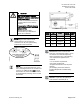
Accessories
Low cost temporary temperature
sensor, 10K Ω thermistor with
RJ11 (1” long), that enables space
control if the permanent room or
duct sensor is not installed (pack of
25).
540-658P25
Duct Temperature Sensor, NTC
10K Ω Type 2, 3" Probe for
Commissioning only.
QAM1030.008P50
Parts for Smoke Control Compliance
Smoke Control Listed Large
Equipment Controller Enclosure
(Long board and ATEC
controllers).
550-002K
UL Listed Class 2 transformer with
120/240/277/480 Vac 50/60 HZ
0.5A primary with hub, and 24 Vac
96VA secondary w/ hub and circuit
breaker.
TR100VA004
NOTE:
For smoke control application, primary
rating is only 120V/60 Hz.
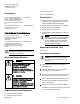
Warning/Caution Notation
WARNING
Personal injury/loss of life may
occur if you do not follow the
procedures as specified.
Risques de blessures graves ou
mortelles, si vous ne suivez pas les
procédures indiquées.
CAUTION
Equipment damage or loss of data
may occur if you do not follow the
procedures as specified.
Risques de dommages ou de pertes
de données, si vous ne suivez pas
les procédures indiquées.
Required Tools and Equipment
Small flat blade screwdriver
3/8-inch open end wrench
Needle nose pliers
1/4-inch poly tubing
Prerequisites
Wiring conforms to NEC and local codes and
regulations. For further information, see the
Wiring Guidelines Manual
(125-3002).
(Optional)
Room temperature sensor installed.
24 Vac Class 2 power available.
Supply power to the unit is OFF.
Any application specific hardware or devices
installed.
NOTE:
A low-cost temporary RTS (540-658P25)
is available that plugs into the RTS port
on the controller, providing temperature
input and actual space control until a
permanent RTS is installed.
Expected Installation Time
30 minutes
Installation Instructions
NOTE:
All wiring must conform to national and
local codes and regulations (NEC, CE,
and so on).
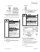
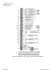
1. Secure the mounting rail in the controller’s
desired location.
2. Place the ESD wrist strap on your wrist and
attach it to a good earth ground.
3. Remove the controller from the static proof bag
and snap it into place on the mounting rail.
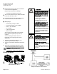
4. If the controller will be used with a field panel,
disconnect the field level network (FLN) trunk
from the field panel.
5. Wire the FLN trunk to the controller. After all
controllers are connected to the FLN, reconnect
the FLN trunk to the field panel.