BACnet LCM-OAVS Room Pressurization with Slowacting Damper Supply and Venturi Exhaust and HW Reheat, Application 6754 Application Note 140-1325 2015-07-07 Building Technologies
Table of Contents Overview ............................................................................................................................. 5 BACnet .............................................................................................................................. 6 Auto Discovery ..................................................................................................................... 7 Auto Addressing ......................................................................
PPCL STATUS .................................................................................................................. 31 Temperature Control Loop ................................................................................................. 31 Alarms ............................................................................................................................ 32 Ventilation Alarm ................................................................................................
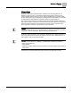
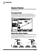
Sequence of Operation BACnet Overview Application 6754 controls pressurization, ventilation, and room temperature in a laboratory room served by one single-duct supply terminal with a reheat coil, one general exhaust terminal, and up to six fume hoods (multiple fume hood flow signals must be averaged using an averaging and scaling module. Pressurization is controlled by maintaining a selected difference between supply and exhaust airflows.
Sequence of Operation BACnet Ventilation and Pressurization Control Drawing. BACnet The controller communicates using BACnet MS/TP protocol for open communications on BACnet MS/TP networks.
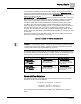
Sequence of Operation Auto Discovery Auto Discovery Auto Discovery allows you to automatically discover and identify PTEC/ATEC controllers on the BACnet MS/TP Network. There are two basic configurations: Devices not configured with an address. (Devices are discovered by their unique serial number.) Devices configured with an address and available for modification. Auto Addressing Auto Addressing allows you to automatically assign device addresses to a PTEC/ATEC controller on the BACnet MS/TP Network.
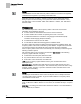
Sequence of Operation Pressurization Control Sequence of Operation The following paragraphs present the sequence of operation for BACnet LCM-OAVS VAV Room Pressurization with HW Reheat, Slow Supply Damper Actuation and Slow Exhaust Venturi Air Valve. Pressurization Control The goal of pressurization control is to maintain a fixed difference between the volumes of total supply air and total exhaust air (see the following figure).
Sequence of Operation Room Airflow Balance To deal with the possibility of unequal flow rate changes, the application includes two new points which allow field adjustment to slow down actuators. SUP MAX RATE effectively limits the speed of the supply actuator; GEX MAX RATE effectively limits the speed of the exhaust actuator. SUP MAX RATE and GEX MAX RATE should be changed to values other than 0 only after a thorough analysis has been made of the job specific scenarios.
Sequence of Operation Occupancy NOTE: VOL DIFFRNC and VOL DIF STPT are positive numbers in a room that is negatively pressurized and negative in a positively pressurized room. Application 6754 has the ability to maintain a different volume differential setpoint during occupied mode than during unoccupied mode. When OCC.UNOCC = OCC, VOL DIF STPT = OCC DIF STPT. When OCC.UNOCC = UNOCC, VOL DIF STPT = UOC DIF STPT.
Sequence of Operation Active Flow Minimums and Maximums The following table shows what is enabled when OCC ENA is at a particular value. OCC ENA Values. OCC ENA (value) 0 (default) Description Both OCC BUTN DI1 and OCC SWIT DI2 are disabled. 1 Only OCC BUTN DI1 is enabled. 2 Only OCC SWIT DI2 is enabled. NOTE: OCC ENA does not allow both OCC BUTN DI1 and OCC SWIT DI2 to be enabled at the same time. If OCC ENA is set greater than 2, it will default to 0.
Sequence of Operation VAV versus CV Control VAV versus CV Control In Application 6754, VAV means that the supply airflow can be varied to provide cooling. CV means the supply airflow is not a source of cooling. However, the supply and general exhaust can still change in CV mode to keep the volume differential setpoint constant. This may be necessary if HOOD VOL is varying. Application 6754 can do either Variable Air Volume control (VAV) or Constant Air Volume Control (CV).
Sequence of Operation Flow Tracking – Supply Tracks Exhaust vs. Exhaust Tracks Supply NOTE: If desired, the LCM can be used without any fume hoods attached. In this case, MAX HOOD VOL should be set to 0 cfm to disable the alarming that would occur if the fume hood flow input drops below 1 Vdc. Flow Tracking – Supply Tracks Exhaust vs.
Sequence of Operation Calculating Exhaust Flow Setpoint TRACK METHOD TRACK METHOD is a point associated with TRACK MODE. TRACK MODE determines which airflow (supply or general exhaust) gets tracked and which airflow does the tracking. TRACK METHOD determines how tracking is accomplished. If TRACK MODE is set to ETS and TRACK METHOD is set for FLOW tracking, the general exhaust flow setpoint is calculated according to the measured value, SUP AIR VOL.
Sequence of Operation Calculating Supply Flow Setpoint When Exhaust Tracks Supply (ETS) flow tracking is used, the general exhaust airflow setpoint is calculated the same during both VAV and CV operation, as follows: To calculate GEX FLO STPT, the controller determines the general exhaust airflow value that pressurizes the room based on the values of VOL DIF STPT, OTHER EXH, OTHER SUP and either SUP FLO STPT or SUP AIR VOL depending on the value of TRACK METHOD.
Sequence of Operation Ventilation – VAV Mode Ventilation – VAV Mode During VAV operation, the ventilation works as follows: OCC SUP MIN, the occupied supply minimum, is used to ensure that the room receives enough supply air for proper ventilation during the occupied mode. UOC SUP MIN is used to ensure that the room receives enough supply air for proper ventilation during the unoccupied mode.
Sequence of Operation Airflow Control When calibration is in progress, CAL AIR equals YES. After calibration, CAL AIR returns to NO. The application uses Autozero Modules connected to AUTOZERO DO8. This means that the supply and general exhaust flow control devices do not close during calibration of the transducers. NOTE: The LCM does not monitor Fume Hood flow changes for 3 seconds during AVS calibration.
Sequence of Operation Airflow Control When initiated, the firmware module sets DMPR STATUS from CAL to RECAL and decrements/increments the damper position (in a reiterative sequence up to four cycles in length) until sensed airflow matches setpoint. NOTE: It is important to realize that while the Damper Status module runs, the damper position point (SUP DMP POS will change in value but the flow point (SUP VOL) might not.
Sequence of Operation Floating Control Actuation Auto-correct Table Statement and Feedback Loop Interaction General exhaust Air Velocity Control – A table statement and the general exhaust air velocity feedback control loop work together to control the general exhaust air velocity. (The table statement values are generated automatically during calibration of the general exhaust Venturi Air Valve.
Sequence of Operation Venturi Air Valve Calibration (Mode 1, 3) Venturi Air Valve Calibration (Mode 1, 3) The calibration table for Venturi Air Valve(s) determines the relationship between airflow and the voltage curve of the actuator. The calibration table initially contains all zeros by default, that is, it contains no calibration information. This section describes how the user initiates a calibration sequence that populates the calibration table with values of flow at given control voltages.
Sequence of Operation Table Access Feature (Mode 1, 3) Venturi Table Statement Example (active values). Exhaust Venturi Air Valve a) cfm volts 368 3.48 452 2.98 476 2.73 504 2.48 572 1.98 604 1.73 618 1.48 712 0.98 760 0.73 800 0.48 904 0 These voltage/flow values constitute the “low flow” element (or “point”) for the Exhaust Venturi Air Valves. They are shown here with factory default values. They are not altered during calibration—they must be set manually.
Sequence of Operation Venturi Table Evaluation and Editing (Mode 1, 3) Venturi Airflow @ 350 fpm. Valve Size in Inches cfm 12 275 Dual 10 380 Dual 12 550 Triple 12 825 During calibration, voltage/flow values are automatically generated. Typically there are 8 or 9 pairs. The first pair of voltage/flow values—the low flow point—is not generated; it must be set manually. The Venturi Valve actuator is then fed the voltages and the application reads the resulting airflows.
Sequence of Operation Venturi Table Evaluation and Editing (Mode 1, 3) Running a successful calibration sequence is one way of changing/updating the active values. You can also edit the table manually. Normally this is not necessary, but if you are having flow control problems you may need to edit the table. In order to manually edit the table statement, you must first know which points in the active table need adjusting.
Sequence of Operation Venturi Table Evaluation and Editing (Mode 1, 3) NOTES: 1. If SUP FLO COEF is 0, the table edit feature uses a supply flow coefficient of 1. 2. If SUPDUCT AREA is 0, the table edit feature uses a supply duct area of 1 square foot. 3. If GEX FLO COEF is 0, the table edit feature uses a general exhaust flow coefficient of 1. 4. If GEXDUCT AREA is 0, the table edit feature uses a general exhaust duct area of 1 square foot.
Sequence of Operation PID Only (Mode 2) NOTE: The factory default value for GEX VLV STAT is NOTCAL which indicates a failure of the calibration or that calibration has not yet been done. The value is set whenever a calibration or table transfer is performed as the last step of the calibration/table transfer. GEX VLV STAT is never used for active control decisions. NOTE: The calibration table initially contains all zeros by default, that is, it contains no calibration information.
Sequence of Operation Open Loop (Mode 3) The direction of actuation, Normally Open or Normally Closed is determined by VENTRUI ACT. Point Flow Volt 1 0 0.0 2 0 0.0 15 0 0.0 16 1200 10.0 Example 1 - Table with CFM End Limit – direct acting It may not be necessary to enter 0 values since 0 values are initially in the table by default when direct acting is selected. Point Flow Volt 1 0 10.0 2 0 10.0 15 0 10.0 16 1200 0.
Sequence of Operation Operating Without a Supply or Exhaust 16 1200 0.0 Example 4 - Table with Voltage End Limits and Low Flow Value – reverse acting You can also manually populate the table with additional values as shown in Example 5 below. In this case, the table becomes indistinguishable from a table generated using the calibration process. Point Flow Volt 1 300 3.0 2 0 0 7 0 0 8 340 3.2 9 390 3.5 10 521 3.8 11 531 4.1 12 598 4.9 13 691 5.8 14 798 7.
Sequence of Operation Heating Safety Heating Safety NOTE: As a safety feature, these applications include MODHTG FLO to ensure that adequate airflow is present before heating coils are energized. When the supply airflow (in fpm as derived from the supply air velocity sensor) is greater than MODHTG FLO, then the internal point “ok_to_mod” is set to Yes and the modulating heating device is allowed to modulate.
Sequence of Operation Room Temperature Offset The application also uses CTL TEMP as the temperature input for the Room Temperature PID Loop. When CTL TEMP is not overridden, then: CTL TEMP = ROOM TEMP + TEMP OFFSET. Room Temperature Offset NOTE: The Room Temperature Offset feature is optional. TEMP OFFSET is a user-adjustable offset that will compensate for deviations between the value of ROOM TEMP and the actual room temperature. This corrected value is displayed in CTL TEMP.
Sequence of Operation Room Unit Operation Room Temperature, Setpoint, RH and CO2 When the digital room unit (Series 2200/2300) is used, SENSOR SEL selects the source for temperature and setpoint and enables a loss of communications indication: – 1 = enables supervision (from the room unit) for fail communications for temperature and setpoint. – 2 = enables supervision (from the room unit) for fail communications for relative humidity.
Sequence of Operation PPCL STATUS Room RH RM RH displays the relative humidity value in percent. RM RH can be used for PPCL in the PTEC or unbundled for control or monitoring purposes. RM RH displays the relative humidity value in percent. PPCL STATUS PPCL STATUS displays LOADED or EMPTY. LOADED = PPCL - programming is present in the controller. A new application number must be assigned (12000 through 12999). EMPTY = NO PPCL - programming is present. The maximum number of PPCL dynamic points is 15.
Sequence of Operation Alarms The range of TEMP LOOPOUT is 0 to 100%. Higher values indicate a need for more cooling (or less heat). The Figure Temperature Control Sequence shows that as the value of TEMP LOOPOUT moves from START to 0%, and the reheat VALVE CMD is modulated from 0 to 100%. VALVE CMD is converted to a voltage and put out on REHEAT A01. The setup points, VALVE CLOSED and VALVE OPEN, tell the controller the voltage range the valve needs to reach at each end of its stroke.
Sequence of Operation Alarms The ventilation alarm, VENT ALM, indicates that there is something wrong with the ventilation to the room. VENT ALM has an adjustable alarm level that can vary with the occupancy status of the room. An adjustable delay timer, VENT ALM DEL, prevents nuisance alarms. VENT ALM is turned on when at least one of the following conditions is true: The supply flow to the room, TOTL SUPPLY, stays below the alarm level, for a time at least equal to VENT ALM DEL.
Sequence of Operation Alarms WARNING To ensure that VOL DIF ALM turns on before the pressure in the room changes sign, DIF ALM DBD must be less than the absolute value of VOL DIF STPT. For example, if negative pressure is desired and VOL DIF STPT equals 70 cfm and DIF ALM DBD is 200 cfm, then the room could go positive by almost 130 cfm without the pressure alarm turning on. In this case, if you want the alarm to turn on before the room changes sign, then you must set DIF ALM DBD to be less than 70 cfm.
Sequence of Operation Actuator Position on Return from Power Failure ALARM DO7 is used to operate a local alarm annunciation device such as a light or horn in or near the room. Inputs can be set up to annunciate alarms from any combination of the following sources: Pressurization alarm point, VOL DIF ALM (To connect VOL DIF ALM to DO 7, set ALM ENA to a value that enables the pressure alarm (4, 5, 6 or 7)).
Sequence of Operation Operation of AVS FAILMODE GEX Valve On a return from power failure, the AOs remain OFF for 5 seconds prior to resuming control. Because of this it is recommended that the General Exhaust Valve be set to Normally Opened for rooms where negative or neutral pressurization is required and Normally Closed for positively pressurized rooms. Setting of the Venturi direction is via VENTURI ACT.
Sequence of Operation Fail Mode Operation If AVS FAILMODE equals 7, the supply Damper will hold. The general exhaust Venturi Air Valve will also hold if a fume hood is present (that is, if MAX HOOD VOL > 0). If a fume hood is absent, then the general exhaust Venturi Air Valve will close if the room is being positively pressurized and open if the room is neutral or negatively pressurized (that is if VOL DIF STPT is equal to or greater than 0).
Sequence of Operation Fail Mode Operation Fume Hood Flow – If MINHOODVOLTS is 1 Volt or higher, HOOD VOL will fail when the LCM receives an invalid (less than .4 Vdc) fume hood flow signal or when the fume hood controller (FHC) loses power or when it loses its flow sensor. If HOOD VOL fails and if VOL DIF STPT is greater than or equal to 0 (negative or neutral pressurization required), the supply and exhaust loops assume a hood exhaust value of 0 cfm and continue to maintain user-defined pressurization.
Sequence of Operation Application Notes Application Notes Supply Only - Operating Without a General Exhaust Box This application can operate without a general exhaust box. If a general exhaust box is not being controlled, set TRACK METHOD to FLOW and set the following points: TRACK MODE to 3. – Without a fume hood attached, use a value of 3 = ETS (exhaust tracks supply) Flow Tracking, should be used for both the occupied and unoccupied modes.
Sequence of Operation Wiring Diagrams Wiring Diagrams Offboard Air Module Wiring. CAUTION The LCM-OAVS has two terminal blocks with terminations numbered identically (terminations 1 through 16). DO NOT mix these up with each other. If the LCM-OAVS is not connected as shown, it is not resistant to electrical surges. It is also susceptible to interference from other equipment. CAUTION A separate power supply is required if a 4-20 mA sensor is used.
Sequence of Operation Wiring Diagrams NOTE: If the voltage/current switch is set to current and a 4 to 20 mA sensor is connected to an AI, then special wiring requirements must be followed. NOTE: The controller’s DOs control 24 Vac loads only. The maximum rating is 12 VA for each DO.
Sequence of Operation Wiring Diagrams BACnet LCM-OAVS Slow Actuation Damper Supply/Venturi Exhaust – Application 6754 Wiring Diagram. 42 Siemens Industry, Inc.
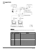
Point Database Application 6754 Point Database Application 6754 Object Type Object Instance (Point Number) Object Name (Descriptor) Factory Default (SI Units) Eng Units (SI Units) Range Active Text Inactive Text AO 1 CTLR ADDRESS 255 -- 0-255 -- -- AO 2 APPLICATION 6792 -- 0-32767 -- -- AO 3 TEMP OFFSET 0.0 (0.0) DEG F (DEG C) -31.75-32 -- -- AI {04} ROOM TEMP 74.0 (23.44888) DEG F (DEG C) 48-111.75 -- -- AO 5 OCC DIF STPT 400 (188.
Point Database Application 6754 Object Type Object Instance (Point Number) Object Name (Descriptor) Factory Default (SI Units) Eng Units (SI Units) Range Active Text Inactive Text AO {31} OCC SUP MAX 3400 (1604.46) CFM (LPS) 0-32764 -- -- AO {32} OCC SUP MIN 340 (160.446) CFM (LPS) 0-32764 -- -- AO {33} OCC GEX MAX 1100 (519.09) CFM (LPS) 0-32764 -- -- AO {34} OCC GEX MIN 600 (283.14) CFM (LPS) 0-32764 -- -- AI {35} SUP AIR VOL 0 (0.
Point Database Application 6754 Object Type Object Instance (Point Number) Object Name (Descriptor) Factory Default (SI Units) Eng Units (SI Units) Range Active Text Inactive Text AO {67} UOC GEX MAX 1000 (471.9) CFM (LPS) 0-32764 -- -- AO {68} UOC GEX MIN 500 (235.95) CFM (LPS) 0-32764 -- -- AI {69} TOTL SUPPLY 0 (0.0) CFM (LPS) 0-32764 -- -- AO 70 SUP P GAIN 0.015 -- 0-4.095 -- -- AO {71} UOC SUP MAX 2200 (1038.
Point Database Application 6754 Object Type Object Instance (Point Number) Object Name (Descriptor) Factory Default (SI Units) Eng Units (SI Units) Range Active Text Inactive Text AO 105 VENTURI ACT 1 -- 0-255 -- -- AO 106 MODHTG FLO 300 (1.524) FPM (MPS) 0-4095 -- -- AO 107 DO DIR.
Point Database (Slave Mode) Application 6792 Point Database (Slave Mode) Application 6792 Object Type Object Instance (Point Number) Object Name (Descriptor) Factory Default (SI Units) Eng Units (SI Units) Range Active Text Inactive Text AO 1 CTLR ADDRESS 255 -- 0-255 -- -- AO 2 APPLICATION 6792 -- 0-32767 -- -- AO 3 TEMP OFFSET 0.0 (0.0) DEG F (DEG C) -31.75-32 -- -- AI {04} ROOM TEMP 74.0 (23.44888) DEG F (DEG C) 48-111.75 -- -- AI {13} ROOM STPT 74.0 (23.
Point Database (Slave Mode) Application 6792 Object Type Object Instance (Point Number) Object Name (Descriptor) Factory Default (SI Units) Eng Units (SI Units) Range Active Text Inactive Text AI {84} AI 5 74.0 (23.496) DEG F (DEG C) 37.5-165 -- -- BO {94} CAL AIR NO -- Binary YES NO AO 95 CAL SETUP 4 -- 0-255 -- -- AO 96 CAL TIMER 12 HRS 0-255 -- -- AO 97 DUCT AREA 1 1.0 (0.09292) SQ. FT (SQ M) 0-6.
Issued by Siemens Industry, Inc. Building Technologies Division 1000 Deerfield Pkwy Buffalo Grove IL 60089 Tel. +1 847-215-1000 Document ID 140-1325 Edition 2015-07-07 © Siemens Industry, Inc., 2015 Technical specifications and availability subject to change without notice.