
Application

Sequence of Operation
Table Access Feature (Mode 1, 3)
21
Siemens Industry, Inc.
BACnet LCM-OAVS, Application 6754
140-1325
2015-07-07
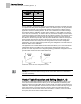
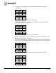
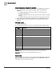
Venturi Table Statement Example (active values).
Exhaust Venturi Air Valve
cfm
volts
368
3.48
452
2.98
476
2.73
504
2.48
572
1.98
604
1.73
618
1.48
712
0.98
760
0.73
800
0.48
904
0
a)
These voltage/flow values constitute the “low flow”
element (or “point”) for the Exhaust Venturi Air
Valves. They are shown here with factory default
values. They are not altered during calibration—they
must be set manually. However, they only need to be
set if the Venturi Air Valve is going go be operating at
low flow settings of less than 350 fpm. Otherwise,
they can be left at default and ignored.
NOTE:
The first pair (or “point”) of flow/voltage values in the table statement is the low flow
point. It is provided for low flow situations where airflow through the Venturi Air Valve
must be controlled at velocities less than 350 fpm. Otherwise, this point can be left at
factory default of 0 cfm and 0V (10V if exhaust) and ignored, as is the case in the
example table statement in the Table
Venturi Table Statement Example
. See the
Table
Venturi Air Valve Table Statement
for how to manually set this point.
If there is a low flow cfm value, it is taken either from the room schedule or the Venturi
Air Valve housing. Cubic feet per minute (cfm) flows in this range (where velocity
equals less than 350 fpm) and related voltages must be determined and/or confirmed
with help from a balancer. See the Table
Venturi Airflow @ 350 fpm
for cfm flows
equal to 350 fpm. The following equation associates airflow to air velocity:
Airflow (cfm) = Velocity (fpm) × Duct Area (sq ft) × Flow Coefficient.
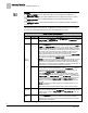
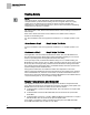
Venturi Airflow @ 350 fpm.
Valve Size in
Inches
cfm
5
48
6
69
8
122
10
191