
Application

Sequence of Operation
PID Only (Mode 2)
25
Siemens Industry, Inc.
BACnet LCM-OAVS, Application 6754
140-1325
2015-07-07
NOTE:
The factory default value for GEX VLV STAT is NOTCAL which indicates a failure of
the calibration or that calibration has not yet been done. The value is set whenever a
calibration or table transfer is performed as the last step of the calibration/table
transfer. GEX VLV STAT is never used for active control decisions.
NOTE:
The calibration table initially contains all zeros by default, that is, it contains no
calibration information. When the application detects all zeros, the application
operates, but runs with only PID control. If PID only control is satisfactory for a given
job, there is no need to populate the table. Should it be necessary, a populated table
can later be edited back to all zeroes to force PID only control.
PID Only (Mode 2)
NOTE:
The default P gain value is intended for PID operation in conjunction with the Venturi
table. The P gain and Venturi table work together to provide an appropriate response
to setpoint changes. When operating without the Venturi table in PID Only mode, the
application is slower to respond. Therefore, you should adjust the P gain as needed
when operating in PID Only mode to ensure acceptable performance.
The Venturi calibration table initially contains all zeros by default, that is, it contains no
calibration information. When the application detects a zero flow for the sixteenth entry
(the table entry with the highest flow), the application does operate, but runs with only
PID control. If PID only control is satisfactory for a given job, there is no need to
populate the Venturi tables.
Open Loop (Mode 3)
This application can operate in open loop mode. In open loop control, there is no
airflow sensor to provide an actual airflow measurement. Instead, operation is based
completely on the values in the Venturi table. For example, if the actuator’s setpoint is
600 cfm, the application will use the Venturi table to derive the voltage setting that
generates a flow of 600 cfm and then set the actuator to that voltage to generate the
desired flow. Assuming the table has accurate entries, the flow (if it were to be
measured) would be at setpoint.
Internally within the application, with open loop control, the flow is always assumed to
be at setpoint As a result there is virtually no difference between flow tracking and
setpoint tracking when the actuator being tracked is operating open loop.
Set
G OPEN LOOP to YES to indicate that the general exhaust actuator is to operate
open loop. Setting this enable point to
YES will suppress the AVS failure indication that
otherwise would occur when no airflow sensor is connected.
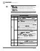
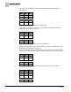
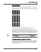
When operating open loop, there is no flow sensor for use in the calibration sequence.
Instead, the Venturi table values are directly input by the user. If the Venturi Valve has
end points for calibration such as 1200 cfm at end voltage, and an implied lower range
of 0 cfm at its other end of the voltage range, you should enter this information into
Point 16, as shown in Example 1 and 2 below.