
Application


Sequence of Operation
Alarms
32
Siemens Industry, Inc.
BACnet LCM-OAVS, Application 6754
140-1325
2015-07-07
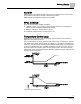
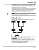
The range of TEMP LOOPOUT is 0 to 100%. Higher values indicate a need for more
cooling (or less heat). The Figure
Temperature Control Sequence
shows that as the
value of TEMP LOOPOUT moves from START to 0%, and the reheat VALVE CMD is
modulated from 0 to 100%. VALVE CMD is converted to a voltage and put out on
REHEAT A01. The setup points, VALVE CLOSED and VALVE OPEN, tell the
controller the voltage range the valve needs to reach at each end of its stroke.
The controller modulates the cooling flow in sequence with the valve. In this
application, temperature control is not the only factor affecting the supply airflow—
room pressurization has a higher priority. Therefore, the temperature control sequence
does not calculate the supply flow setpoint. Instead, it calculates the amount of supply
airflow needed for cooling (TEMP CTL VOL). If this value is compatible with correct
room pressurization, it is used as the supply flow setpoint. If not, the actual setpoint,
SUP FLO STPT, may be higher or lower than TEMP CTL VOL. As the value of TEMP
LOOPOUT moves from START to 100%, TEMP CTL VOL is modulated from the
supply minimum to the supply maximum. (During the occupied period, the supply
minimum is OCC SUP MIN and the supply maximum is OCC SUP MAX. During the
unoccupied period, the supply minimum is UOC SUP MIN and the supply maximum is
UOC SUP MAX.
The temperature sequencing point, START, determines what part of the operating
range is used for cooling and reheat. By default, it is set to allow 50% of the range to
cooling and 50% to reheat. You can alter that balance so it matches the heating and
cooling capacities of the equipment. For instance, if the reheat valve has three times
the effect of the cooling flow, then setting START to 75% gives an approximately
uniform thermal affect across the range of TEMP LOOPOUT. In some cases, this
makes it easier to tune the PID loop.
When the controller is operating in the constant volume mode, TEMP LOOPOUT is not
allowed to get numerically bigger than the value of START. This means that the
application will control the temperature only by modulating the reheat valve; it will make
no attempt to control temperature by varying the airflow in the space. During constant
volume control, TEMP CTL VOL will remain equal to zero.
Alarms
The controller is equipped with ventilation and pressurization alarms. It does not
contain temperature alarms. The controller’s alarms are designed to:
Inform room occupants of hazards.
Inform building operation personnel that the system is not functioning correctly.
Supply data for documenting laboratory safety records through trending.
These alarms can be annunciated locally and/or broadcast across a network.
Ventilation Alarm
The alarm level depends on whether the room is occupied or vacant. When the
OCC.UNOCC point indicates occupancy, the OC V ALM LVL is used. When the
OCC.UNOCC point indicates vacancy, the UC V ALM LVL is used.
NOTE:
In the following discussion, the currently active supply flow minimum is OCC SUP
MIN during occupancy and UOC SUP MIN during the unoccupied period. Likewise,
the currently active general exhaust box minimum is OCC GEX MIN during
occupancy and UOC GEX MIN during the unoccupied period.