
Application
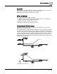


Sequence of Operation
Actuator Position on Return from Power Failure
35
Siemens Industry, Inc.
BACnet LCM-OAVS, Application 6754
140-1325
2015-07-07
ALARM DO7 is used to operate a local alarm annunciation device such as a light or
horn in or near the room. Inputs can be set up to annunciate alarms from any
combination of the following sources:
Pressurization alarm point, VOL DIF ALM
(To connect VOL DIF ALM to DO 7, set ALM ENA to a value that enables the
pressure alarm (4, 5, 6 or 7)).
Ventilation alarm point, VENT ALM
(To connect VENT ALM to DO 7, set ALM ENA to a value that enables the
ventilation alarm (1, 3, 5 or 7)).
DI connected to a switch in the room, ALM SWIT DI6
(To connect ALM SWIT DI6 to DO 7, set ALM ENA to a value that enables the
Alarm Switch (2, 3, 6 or 7)).
Network alarm point, NET ALM CMD
(NET ALM CMD is always enabled for local annunciation.)
ALARM DO7 turns ON if any of the enabled alarm sources indicate an alarm. ALARM
DO7 cannot be overridden.
NET ALM CMD can be commanded with the workstation software or PPCL to send an
alarm state from the field panel. This makes it possible to program unique alarm
criteria and annunciate alarms in specific rooms.
Network Annunciation
If the LCM is connected to a field panel, alarms can be reported using the workstation
software, or by using a printer that is set up in a building manager’s office to receive
alarms. Points in the controller must be entered in the field panel’s point database
(referred to as unbundling) and defined as alarmable. For example, if the room
pressurization alarm (VOL DIF ALM) is unbundled in a field panel and a pressurization
alarm is triggered, an alarm will be annunciated across the network.
Alarms in Open Loop Mode
When operating a Venturi valve in open loop mode, there is no sensor to measure
actual flow. Instead, flow estimates are based on the current commanded valve
position.
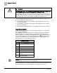
Actuator Position on Return from Power Failure
Supply Damper
On a return from power failure, the damper-command DOs (DOs1 through 2) remain
OFF for 5 seconds prior to resuming control. Because of this it is recommended that
the Supply Damper Motor Setup be set to Enabled (normally closed) for rooms where
negative or neutral pressurization is required and Enabled and Reversed (normally
open, where the actuator is retracted) for positively pressurized rooms.
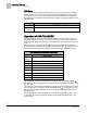
Additive Values that Determine the Value of MTR SETUP
Not Used
Enabled
Enabled and
Reversed
Motor 1 (supply damper – DO 1 and DO 2)
0
1
3