
Installation Instructions

Installation Instructions
Document No. 546-00091
Rev. 2, February, 2000
Laboratory Analog Output-Pneumatic (AO-P)
Module
Page 1 of 2
Product Description
The Laboratory Analog Output-Pneumatic (AO-P)
Module is the electro-pneumatic interface between
the Fume Hood Controller and the Pneumatic
Damper Actuator. The AO-P module applies specific
air pressure to the pneumatic actuator to move the
damper to its proper position.
Product Numbers
546-00090
Required Tools
• Medium duty drill
• Small socket set
• Small flat-blade screwdriver
• Medium flat-blade screwdriver
• Drill set
Prerequisites
• Placement of supply line and actuator with
1/4-inch (6 mm) tubing
• Fume Hood Controller is installed
• Optional, for conduit or metal enclosure
installations only
Expected Installation Time
15 minutes
Instructions
The Analog Output-Pneumatic (AO-P) Module
Installation Instructions consist of the following four
sections:
1. Mounting
2. Pneumatic Piping
3. General Wiring
4. Metal Enclosure Applications
NOTE:
If your installation requires conduit, then
proceed directly to Section 4.
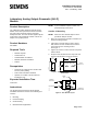
Section 1: Mounting
NOTE:
Mount the AO-P module adjacent to the
pneumatic damper actuator.
1. Place the snap track for the AO-P module in the
desired mounting position.
2. Using both of the self-taping screws, electric
drill, and the 1/4-inch nut driver bit, mount the
snap track onto the mounting surface.
See Figure 1.
3. Tighten the screws to ensure that the snap track
will not vibrate.
4. Snap the AO-P module into the snap track and
verify that the module is securely fastened.
AO-P MODULE
REMOVED FOR CLARITY
2.00"
(50.8mm)
4.00"
(101.6mm)
MOUNTING
HOLES (2 PLS.)
1.50"
(38.1mm)
3.00"
(76.2mm)
FUM0244R1
Figure 1. AO-P Module Mounting Holes and
Dimensions.
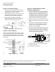
SUPPLY
COMMON
EXHAUST
SUPPLY
S
(SUPPLY)
18-30 PSI
S (SUPPLY)
FILTER ASSY.
R
(ACTUATOR)
R (ACTUATOR)
EXHAUST
LED
MUFFLER ON
EXHAUST VALVE
SUPPLY
LED
EXHAUST
FUM0242R1
Figure 2. AO-P Module Layout.