
Installation Instructions

Document No. 546-00091
Installation Instructions
Rev. 2, February, 2000
Information in this publication is based on current specifications. The company reserves the right to make changes in specifications and
models as design improvements are introduced. © 2000 Siemens Building Technologies, Inc.
Siemens Building Technologies, Inc.
Landis & Staefa Division
1000 Deerfield Parkway
Buffalo Grove, IL 60089-4513
U.S.A.
Document No.: 546-00091
Printed in the U.S.A.
Page 2 of 2
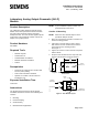
Section 2: Pneumatic Piping
1. Remove the filter and tubing assembly from the
box and push the end with the tubing onto the S
(Supply) fitting of the AO-P module.
2. Using 1/4-inch O.D. tubing, connect the 18 to 30
PSI air supply to the filter inlet that was just
installed on the AO-P module. See Figure 3.
3. Using 1/4-inch O.D. tubing, connect the
pneumatic damper actuator to the R (Actuator)
fitting on the AO-P module. See Figure 3.
Figure 3. AO-P Module Piping Connections.
Section 3: General Wiring
Using 3 conductor 20 AWG cable, connect the wire
from the AO-P module to the Fume Hood Controller
Board terminal block labeled TB3. Screw the wires
into the provided terminal block to secure the wires.
SeeFigure4.
Figure 4. AO-P Wiring.
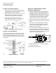
Section 4: Conduit Wiring or Metal
Enclosure Applications
1. Mount the snap track to the holes provided in
the base of enclosure 544-294 (PXP Transducer
Enclosure this part is ordered separately). To
accomplish this step, remove the cover. Remove
the existing snap track and bend the small tabs
in the base of the enclosure down. Install the
provided snap track with the AO-P Module.
2. Mount the enclosure in its final location using the
dimensions below. Snap the AO-P into the snap
track.
3. See
Section 2: Pneumatic Piping instructions
,
and mount the pneumatic piping. The holes in
the side of the enclosure will line up with the
fittings on the AO-P Module.
4. See
Section 3: General Wiring instructions
, and
wire the connections. See Figure 4 and Figure 5.
If the installation requires conduit, then mount a
standard 1/2-inch conduit fitting to the enclosure
and secure the conduit to the fitting.
5.00" (127.0mm)
3.70"
(94.0mm)
SUPPLY
COMMON
EXHAUST
SUPPLY
S
(SUPPLY)
18-30 PSI
R
(ACTUATOR)
EXHAUST
FUM0240R1
Figure 5. Conduit Wiring.
5. Replace the cover to the enclosure and tighten
the two screws down.
The installation is now complete.