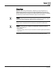
BACnet LCM-OAVS Room Pressurization with Fastacting Damper Actuation (One Exhaust, One Supply) and Hot Water Reheat, Application 6751 Application Note 140-1331 2015-07-07 Building Technologies
Table of Contents Overview ............................................................................................................................. 5 BACnet .............................................................................................................................. 6 Auto Discovery ..................................................................................................................... 7 Auto Addressing ......................................................................
Damper Position on Return from Power Failure ................................................................ 23 Operation of AVS FAILMODE ........................................................................................... 24 Fail Mode Operation .......................................................................................................... 25 Application Notes ...............................................................................................................
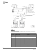
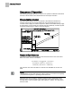
Overview BACnet Overview Application 6751 controls pressurization, ventilation, and room temperature in a laboratory room served by one single-duct supply terminal with a reheat coil, one general exhaust terminal, and up to six fume hoods (multiple fume hood flow signals must be averaged using an averaging and scaling module. Pressurization is controlled by maintaining a selected difference between supply and exhaust airflows.
Overview BACnet Ventilation and Pressurization Control Drawing. BACnet The controller communicates using BACnet MS/TP protocol for open communications on BACnet MS/TP networks.
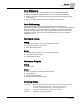
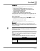
Overview Auto Discovery Auto Discovery Auto Discovery allows you to automatically discover and identify PTEC/ATEC controllers on the BACnet MS/TP Network. There are two basic configurations: Devices not configured with an address. (Devices are discovered by their unique serial number.) Devices configured with an address and available for modification. Auto Addressing Auto Addressing allows you to automatically assign device addresses to a PTEC/ATEC controller on the BACnet MS/TP Network.
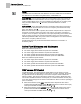
Sequence of Operation Pressurization Control Sequence of Operation The following paragraphs present the sequence of operation for BACnet LCM-OAVS VAV Room Pressurization with HW Reheat and Fast Damper Actuation. Pressurization Control The goal of pressurization control is to maintain a fixed difference between the volumes of total supply air and total exhaust air (see the following figure).
Sequence of Operation Occupancy Occupancy The controller keeps track of the occupancy status of the room and uses that information for the following purposes: To select minimum and maximum flow rates for each air terminal. To select whether the controller is operating in the VAV or CV mode. To determine whether the controller is using Supply Tracks Exhaust (STE) or Exhaust Tracks Supply (ETS) flow tracking. To determine the value of VOL DIF STPT.
Sequence of Operation Active Flow Minimums and Maximums NOTE: OCC ENA does not allow both OCC BUTN DI1 and OCC SWIT DI2 to be enabled at the same time. If OCC ENA is set greater than 2, it will default to 0. OCC SWIT DI2 – The occupancy switch (dry contact switch in the room) can be any device that closes the switch when the room is occupied (occupancy sensor, extra contact on light switch, and so on). The controller uses this input for occupancy if the setup point OCC ENA is set to 2.
Sequence of Operation Fume Hood Flow Input Depending on how VOLUME STATE is configured, Application 6751 can operate as either a Variable Air Volume (VAV) LCM or a constant volume (CV) LCM. Also, these operational modes can vary between the occupied and unoccupied periods, if desired. The following table shows what the application does when VOLUME STATE is at a particular value. VOLUME STATE Values. VOLUME STATE (value) 0 Description Always Constant Volume.
Sequence of Operation Flow Tracking – Supply Tracks Exhaust vs. Exhaust Tracks Supply Supply Tracks Exhaust mode is useful when trying to maintain negative pressurization. During Supply Tracks Exhaust, the supply air volume "tracks" or follows the exhaust air volume. If the exhaust air is "broken" (for instance, if the general exhaust airflow control device is stuck open or stuck closed), the supply air volume will be adjusted so that VOL DIF STPT is maintained as much as possible.
Sequence of Operation Calculating Exhaust Flow Setpoint This feature prevents the incorrect pressurization of rooms that lack the required general exhaust capacity. The changeover is based on the error of the general exhaust flow loop. If the error is greater than FAIL LIMIT, and stays that way for a time longer than FAIL TIME, then the module changes from STPT tracking to FLOW tracking. It stays in that mode until the error comes back to zero, then switches back to the STPT tracking mode.
Sequence of Operation External Flow Values During CV operation, the controller ignores TEMP CTL VOL. Instead, it calculates SUP FLO STPT based on the value of the active supply flow minimum and the amount of supply airflow needed to pressurize the room. NOTE: Regardless of the flow tracking method (STE or ETS) being used, the controller does not let the actual supply airflow rise above the currently active supply airflow maximum.
Sequence of Operation Ventilation – Constant Volume Mode Ventilation – Constant Volume Mode During Constant Volume (CV) operation, the active supply airflow minimum is used to ensure that the room always receives enough supply air for proper ventilation. If necessary, the application raises the general exhaust flow to keep the supply flow from dropping below the minimum. See Calculating Exhaust Flow Setpoint for more information. In CV mode the active supply minimum is the setpoint.
Sequence of Operation Floating Control Actuation Auto-correct Each damper may be set up for normally open or normally closed operation. To enhance stable flow control, an advanced algorithm is used to calculate a controllable setpoint as the value approaches zero cfm (lps). When the flow is slightly below the setpoint, the LCM sets the damper command to a small positive number to open the damper gradually.
Sequence of Operation Room Temperature and Setpoint If the application uses hot water heat rather than electric heat, then MODHTG FLO may be set lower than the default value of 300. This allows reheating to occur even if the box is operating below its designated minimum flow setting. In the open loop mode, the measured airflow is always 0. To re-enable heating, the MODHTG FLO value must be set to 0.
Sequence of Operation Room Unit Identification Room Unit Identification For Analog Room Units (Series 1000) – The revision number is visually identified by its case. For Digital Room Units (Series 200/2300 Firmware Revision 25 or earlier) – The revision number displays for 5 seconds when the room unit is first powered up. These room units will display laptop when a laptop is connected and will no longer update room temperature sensor values.
Sequence of Operation PPCL STATUS SENSOR SEL Value * Description 7 Digital Room Unit, RH, CO2, 10K 8 Analog Room Unit, 100K 9 Digital Room Unit, 100K 11 Digital Room Unit, RH, 100K 13 Digital Room Unit, CO2, 100K 15 Digital Room Unit, RH, CO2, 100k 16 (Not used) Example 1: Digital Room Unit with temperature, RH, CO2 and 10K thermistor. 1+2+4+0 = 7 Example 2: Analog Room unit with 100K thermistor. 0+0+0+8 = 8 Room CO2 RM CO2 displays the CO2 value in units of parts-per-million (PPM).
Sequence of Operation Temperature Control Loop Temperature Control Sequence. The range of TEMP LOOPOUT is 0 to 100%. Higher values indicate a need for more cooling (or less heat). The Figure Temperature Control Sequence shows that as the value of TEMP LOOPOUT moves from START to 0%, and the reheat VALVE CMD is modulated from 0 to 100%. VALVE CMD is converted to a voltage and put out on REHEAT A01.
Sequence of Operation Alarms Alarms The controller is equipped with ventilation and pressurization alarms. It does not contain temperature alarms. The controller’s alarms are designed to: Inform room occupants of hazards. Inform building operation personnel that the system is not functioning correctly. Supply data for documenting laboratory safety records through trending. These alarms can be annunciated locally and/or broadcast across a network.
Sequence of Operation Alarms Pressurization Alarm The pressurization alarm, VOL DIF ALM indicates that the difference between supply and exhaust flow is not what it should be, or that the controller can't calculate the flow difference, VOL DIFFRNC, because it has lost a flow signal. The Figure Failure Mode Sequence lists reasons why VOL DIFFRNC may fail. The pressurization alarm point is turned on when at least one of the following conditions occurs: VOL DIFFRNC has a status of Failed.
Sequence of Operation Damper Position on Return from Power Failure ALARM ENA Values. ALARM ENA 5 Vent Alarm and Dif Alarm are enabled. 6 Alarm Switch and Dif Alarm are enabled. 7 Vent Alarm, Alarm Switch, and Dif Alarm are all enabled. NOTE: If ALARM ENA is set greater than 7, it will default to 0. ALM ENA is additive. For example, if ALM ENA equals 5, then either a ventilation or a pressurization alarm will activate ALARM DO7, but the alarm switch will not.
Sequence of Operation Operation of AVS FAILMODE Damper (GEX DMPR DIR) be set to NOPEN for rooms where negative or neutral pressurization is required and NCLOSE for positively pressurized rooms. The default for the SUP DMPR DIR is NCLOSE. The default for GEX DMPR DIR is NOPEN. Operation of AVS FAILMODE AVS FAILMODE is an enumerated point that describes how the supply Damper and the general exhaust Damper will respond if one or both Air Velocity Sensors (AVS) fail.
Sequence of Operation Fail Mode Operation Fail Mode Operation If one of the controller’s accessories (inputs) fails, a failure mode sequence is initiated that leads to the failure of VOL DIFFRNC. The following figure shows the order in which points will fail. * If MAX HOOD VOL is set to 0, a “Failed” status of HOOD VOL will not initiate a failure in TOTL EXHAUST or VOL DIFFRNC. See Fume Hood Flow Input.
Sequence of Operation Application Notes Laboratory Room Controller – If the LCM power fails, all actuators default to their userdefined fail-safe states. Since there is no power to the controller, no LEDs are available. Electronic Actuator – If the actuator fails, typically, flow control is lost and alarms are triggered. Upon loss of power or control signal to the actuator, it will move to its fail-safe position.
Sequence of Operation Wiring Diagram Operating Without a Supply Box This application can operate without a supply box. If a supply box is not being controlled, set TRACK METHOD to FLOW and set the following points: TRACK MODE to 3. (a value of 3 = ETS Flow Tracking, should be used for both the occupied and unoccupied modes). SUP FLO COEF to 0. When SUP FLO COEF equals 0, SUP AIR VOL will always read 0, but will never show as Failed. OCC SUP MIN and UOC SUP MIN to 0.
Sequence of Operation Wiring Diagram Wiring for AI with a 4 to 20 mA Sensor. CAUTION Each 4-20 mA sensor requires a SEPARATE dedicated power limited 24 Vdc power supply. DO NOT use the same transformer to power both the sensor and the controller. NOTE: If the voltage/current switch is set to current and a 4 to 20 mA sensor is connected to an AI, then special wiring requirements must be followed. NOTE: The controller’s DOs control 24 Vac loads only. The maximum rating is 12 VA for each DO.
Sequence of Operation Wiring Diagram BACnet LCM-OAVS VAV Room Pressurization with Hot Water Reheat and Fast Damper Actuation (One Exhaust, One Supply) – Application 6751 Wiring Diagram. 29 Siemens Industry, Inc.
Point Database Application 6751 Point Database Application 6751 Object Type Object Instance (Point Number) Object Name (Descriptor) Factory Default (SI Units) Eng Units (SI Units) Range Active Text Inactive Text AO 1 CTLR ADDRESS 255 -- 0-255 -- -- AO 2 APPLICATION 6792 -- 0-32767 -- -- AO 3 TEMP OFFSET 0.0 (0.0) DEG F (DEG C) -31.75-32 -- -- AI {04} ROOM TEMP 74.0 (23.44888) DEG F (DEG C) 48-111.75 -- -- AO 5 OCC DIF STPT 400 (188.
Point Database Application 6751 Object Type Object Instance (Point Number) Object Name (Descriptor) Factory Default (SI Units) Eng Units (SI Units) Range Active Text Inactive Text AI {30} GEX AIR VOL 0 (0.0) CFM (LPS) 0-32764 -- -- AO {31} OCC SUP MAX 3400 (1604.46) CFM (LPS) 0-32764 -- -- AO {32} OCC SUP MIN 340 (160.446) CFM (LPS) 0-32764 -- -- AO {33} OCC GEX MAX 1100 (519.09) CFM (LPS) 0-32764 -- -- AO {34} OCC GEX MIN 600 (283.
Point Database Application 6751 Object Type Object Instance (Point Number) Object Name (Descriptor) Factory Default (SI Units) Eng Units (SI Units) Range Active Text Inactive Text AO {67} UOC GEX MAX 1000 (471.9) CFM (LPS) 0-32764 -- -- AO {68} UOC GEX MIN 500 (235.95) CFM (LPS) 0-32764 -- -- AI {69} TOTL SUPPLY 0 (0.0) CFM (LPS) 0-32764 -- -- AO 70 SUP P GAIN 0.04 -- 0-4.095 -- -- AO {71} UOC SUP MAX 2200 (1038.
Point Database Application 6751 Object Type Object Instance (Point Number) Object Name (Descriptor) Factory Default (SI Units) Eng Units (SI Units) Range Active Text Inactive Text AO 106 MODHTG FLO 300 (1.524) FPM (MPS) 0-4095 -- -- AO 107 DO DIR.REV 0 -- 0-255 -- -- AI {108} RM RH 50 PCT 0-102 -- -- AO 117 MINHOODVOLTS 1 VOLTS 0-10.
Point Database (Slave Mode) Application 6792 Point Database (Slave Mode) Application 6792 Object Type Object Instance (Point Number) Object Name (Descriptor) Factory Default (SI Units) Eng Units (SI Units) Range Active Text Inactive Text AO 1 CTLR ADDRESS 255 -- 0-255 -- -- AO 2 APPLICATION 6792 -- 0-32767 -- -- AO 3 TEMP OFFSET 0.0 (0.0) DEG F (DEG C) -31.75-32 -- -- AI {04} ROOM TEMP 74.0 (23.44888) DEG F (DEG C) 48-111.75 -- -- AI {13} ROOM STPT 74.0 (23.
Point Database (Slave Mode) Application 6792 Object Type Object Instance (Point Number) Object Name (Descriptor) Factory Default (SI Units) Eng Units (SI Units) Range Active Text Inactive Text AI {84} AI 5 74.0 (23.496) DEG F (DEG C) 37.5-165 -- -- BO {94} CAL AIR NO -- Binary YES NO AO 95 CAL SETUP 4 -- 0-255 -- -- AO 96 CAL TIMER 12 HRS 0-255 -- -- AO 97 DUCT AREA 1 1.0 (0.09292) SQ. FT (SQ M) 0-6.
Issued by Siemens Industry, Inc. Building Technologies Division 1000 Deerfield Pkwy Buffalo Grove IL 60089 Tel. +1 847-215-1000 Document ID 140-1331 Edition 2015-07-07 © Siemens Industry, Inc., 2015 Technical specifications and availability subject to change without notice.