
Basic Documentation
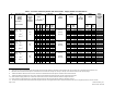

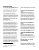

Table Of Contents

Technology Report
March, 2003
Siemens Industry, Inc. Page 1 of 8
VAV Laboratory Room Airflow
The Lowdown on Turndown
Airflow Turndown
Airflow control ranges are normally expressed in
terms of the required maximum and minimum
attainable airflow rate. When this airflow rate is
expressed as a simple ratio, it is commonly referred
to as the turndown ratio or just turndown. For
instance, if an air terminal and its associated control
system provides fully modulated airflow control from
400 cfm up to 2000 cfm, the maximum-to-minimum
airflow ratio can be expressed as 5-to-1 since the
maximum airflow is 5 times the minimum airflow.
Therefore, the turndown is stated as 5:1.
Turndown is commonly used as a convenient way to
express the airflow control needed for specific types
of applications without the necessity of having to refer
to the specific maximum and minimum airflow rates
involved. For instance, specifying that all VAV fume
hood exhausts must be controlled over a 5-to-1
turndown ratio means the exhaust airflow must be
modulated so that the minimum fume hood exhaust
will be one fifth of the maximum exhaust. This
minimum to maximum exhaust airflow relationship
then applies to every fume hood even though
different sizes of fume hoods have different airflow
ranges.
Turndown Misconceptions
As simple as the concept of turndown may seem, it
has led to considerable misunderstanding in the
HVAC industry, and especially with regard to VAV
laboratory ventilation applications. For instance, if a
specific air terminal has a maximum to minimum
airflow range from 3200 cfm down to 400 cfm, it
would have a turndown ratio of 8-to-1. If another air
terminal has the same maximum airflow of 3200 cfm
but a minimum airflow of 200 cfm, its turndown ratio
would be 16-to-1 or twice that of the 8-to-1 unit. A
common but erroneous assumption is that the 16-to-1
unit provides twice the airflow range that the 8-to-1
unit can provide. Figure 1 shows a graphic
c
omparison of these two turndown ratios. Note the
small actual airflow difference between them.
3200 CFM
3000 CFM
2800 CFM
2600 CFM
2400 CFM
2200 CFM
2000 CFM
1800 CFM
1600 CFM
1400 CFM
1200 CFM
1000 CFM
800 CFM
600 CFM
400 CFM
200 CFM
0 CFM
16 : 1
TURNDOWN
8 : 1
TURNDOWN
Figure 1. Comparison Between 16:1 and 8:1
Turndown Ratios.
Higher turndown ratios have also been erroneously
assumed to be indicative of better control
performance. However, larger turndown ratios do not
positively impact the main control performance
factors such as accuracy, repeatability, low
hysteresis, fast response, etc. Rather, the best
control performance results when a control device
has a range or turndown ratio that closely matches
actual need. For example, precise control of
temperature over a range from 65 to 75 degrees
would more likely be attained from a controller having
a range of 60 to 80 degrees as opposed to one with a
much wider range such as 0 to 120 degrees.
Consider a need to control shaft rotational speed at
1200 rpm. A controller with a range of 500 to 2000
rpm (a 4-to-1 turndown ratio) would most likely
provide better control than one with a range of 200 to
5000 rpm (a 25-to-1 turndown ratio).
Document No. 1
49-978