
Installation Instructions

Document No. 540-320
Installation Instructions
July 15, 2009
540-804
Constant Volume
Controller—Electronic Output
with Autozero Module for Trane
540-103C Constant Volume
Controller—Electronic Output
with Secure Mode
540-104C Constant Volume
Controller—Electronic Output
with Autozero Module and Secure
Mode
CAUTION:
Keep the unit in its static-proof bag until
installation.
Accessories
540-628P25
(pack of 25)
Low cost temporary temperature
sensor that enables space control if
the permanent room or duct sensor is
not installed.
Parts for CE Compliance:
550-705
Clamp-on ferrite filter (10 pack)
588-100 series
Approved 2-RJ11 RTS cable in 25’,
50’, or 100’ (7.6-m, 15.2-m, 30.48-m)
.
540-155
Metal Small Equipment Controller
Enclosure
550-002
Large Equipment Controller Enclosure
Warning/Caution Notations
CAUTION:
Equipment damage or loss of data may
occur if you do not follow the procedures
as specified.
Expected Installation Times
10 minutes.
Required Tools and Materials
• Flat-blade screwdr
iver (1/8-inch blade width).
•Smallflat-blade screwdriver
• Cabling and connectors. See the section.
• Cordless drill/driver set
Prerequisites
• MBC or RBC enclosure mounted with at least
one open slot on the C-BUS and AC power
connected.
• CE Compliance requirements met, if needed.
• Termination blocks installed, if any.
• Authorized modem installed if connection to a
public telephone network is required.
• One 115V or 230V receptacle (depending on
device) to power the Trunk Interface II.
If the controller is being installed on a box
with1ormorestagesofelectricheat,
the 550-809 MOV with pre-terminated
spade connectors must be installed across
the manufacturer-supplied airflow switch.
MOV’s can be installed at the time the
controller is factory mounted; coordinate
with the box manufacturer prior to order
placement. For field installation, see Metal
Oxide Varistor Kit Installation Instructions
(540-986).
Instructions
All wiring must conform to NEC and local
codes and regulations.
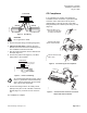
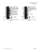
1. Secure the mounting rail (Figure 1) in the
controller’s desired location.
2. Place the ESD wrist strap on your wrist and attach
it to a good earth ground.
3. Remove the controller from the static proof bag
and snap it into place on the mounting rail.
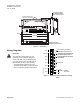
4. Connect the FLN (Figure 2).
Page 2 of 6 Siemens Building Technologies, Inc.