BACnet LCM-OAVS Room Pressurization with Two Fast-acting Venturi Air Valves (One Exhaust, One Supply) and Hot Water Reheat, Application 6750 Application Note 140-1328 2015-07-07 Building Technologies
Table of Contents Overview ............................................................................................................................. 5 BACnet .............................................................................................................................. 6 Auto Discovery ..................................................................................................................... 7 Auto Addressing ......................................................................
Alarms ............................................................................................................................ 32 Ventilation Alarm ................................................................................................ 32 Pressurization Alarm .......................................................................................... 33 Local Annunciation ............................................................................................. 33 Network Annunciation.......
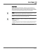
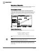
Sequence of Operation BACnet Overview Application 6750 controls pressurization, ventilation, and room temperature in a laboratory room served by one single-duct supply terminal with a reheat coil, one general exhaust terminal, and up to six fume hoods (multiple fume hood flow signals must be averaged using an averaging and scaling module. Pressurization is controlled by maintaining a selected difference between supply and exhaust airflows.
Sequence of Operation BACnet Ventilation and Pressurization Control Drawing. BACnet The controller communicates using BACnet MS/TP protocol for open communications on BACnet MS/TP networks.
Sequence of Operation Auto Discovery Auto Discovery Auto Discovery allows you to automatically discover and identify PTEC/ATEC controllers on the BACnet MS/TP Network. There are two basic configurations: Devices not configured with an address. (Devices are discovered by their unique serial number.) Devices configured with an address and available for modification. Auto Addressing Auto Addressing allows you to automatically assign device addresses to a PTEC/ATEC controller on the BACnet MS/TP Network.
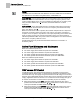
Sequence of Operation Pressurization Control Sequence of Operation The following paragraphs present the sequence of operation for BACnet LCM-OAVS VAV Room Pressurization with HW Reheat and Two Venturi Air Valves. Pressurization Control The goal of pressurization control is to maintain a fixed difference between the volumes of total supply air and total exhaust air (see the following figure).
Sequence of Operation Occupancy Occupancy The controller keeps track of the occupancy status of the room and uses that information for the following purposes: To select minimum and maximum flow rates for each air terminal. To select whether the controller is operating in the VAV or CV mode. To determine whether the controller is using Supply Tracks Exhaust (STE) or Exhaust Tracks Supply (ETS) flow tracking. To determine the value of VOL DIF STPT.
Sequence of Operation Active Flow Minimums and Maximums NOTE: OCC ENA does not allow both OCC BUTN DI1 and OCC SWIT DI2 to be enabled at the same time. If OCC ENA is set greater than 2, it will default to 0. OCC SWIT DI2 – The occupancy switch (dry contact switch in the room) can be any device that closes the switch when the room is occupied (occupancy sensor, extra contact on light switch, and so on). The controller uses this input for occupancy if the setup point OCC ENA is set to 2.
Sequence of Operation Fume Hood Flow Input Depending on how VOLUME STATE is configured, Application 6750 can operate as either a Variable Air Volume (VAV) LCM or a constant volume (CV) LCM. Also, these operational modes can vary between the occupied and unoccupied periods, if desired. The following table shows what the application does when VOLUME STATE is at a particular value. VOLUME STATE Values. VOLUME STATE (value) 0 Description Always Constant Volume.
Sequence of Operation Flow Tracking – Supply Tracks Exhaust vs. Exhaust Tracks Supply Supply Tracks Exhaust mode is useful when trying to maintain negative pressurization. During Supply Tracks Exhaust, the supply air volume "tracks" or follows the exhaust air volume. If the exhaust air is "broken" (for instance, if the general exhaust airflow control device is stuck open or stuck closed), the supply air volume will be adjusted so that VOL DIF STPT is maintained as much as possible.
Sequence of Operation Calculating Exhaust Flow Setpoint This feature prevents the incorrect pressurization of rooms that lack the required general exhaust capacity. The changeover is based on the error of the general exhaust flow loop. If the error is greater than FAIL LIMIT, and stays that way for a time longer than FAIL TIME, then the module changes from STPT tracking to FLOW tracking. It stays in that mode until the error comes back to zero, then switches back to the STPT tracking mode.
Sequence of Operation External Flow Values During CV operation, the controller ignores TEMP CTL VOL. Instead, it calculates SUP FLO STPT based on the value of the active supply flow minimum and the amount of supply airflow needed to pressurize the room. NOTE: Regardless of the flow tracking method (STE or ETS) being used, the controller does not let the actual supply airflow rise above the currently active supply airflow maximum.
Sequence of Operation Ventilation – Constant Volume Mode Closing the general exhaust, which lowers airflow and disables cooling completely. Ventilation – Constant Volume Mode During Constant Volume (CV) operation, the active supply airflow minimum is used to ensure that the room always receives enough supply air for proper ventilation. If necessary, the application raises the general exhaust flow to keep the supply flow from dropping below the minimum.
Sequence of Operation Table Access Feature (Mode 1, 3) Fully operational supply and general exhaust airflow systems. Supply and general exhaust Air Velocity Sensors are calibrated and working normally (SUP AIR VOL and GEX AIR VOL cannot be Failed). The supply or general exhaust Venturi Air Valve is calibrated by setting CAL SUP VLV or CAL GEX VLV to YES. Calibration proceeds automatically and takes about 3 minutes, after which CAL SUP VLV (or CAL GEX VLV) returns to NO.
Sequence of Operation Table Access Feature (Mode 1, 3) Venturi Table Statement Example (active values). a) Supply Venturi Air Valve General exhaust Venturi Air Valve cfm volts cfm volts 373 4.57 452 2.98 382 5.04 476 2.73 418 5.51 504 2.48 521 6.46 572 1.98 531 6.93 604 1.73 598 7.4 618 1.48 777 8.34 712 0.98 861 8.81 760 0.73 980 9.28 800 0.
Sequence of Operation Venturi Table Evaluation and Editing (Mode 1, 3) Venturi Airflow @ 350 fpm. Valve Size in Inches cfm 10 191 12 275 Dual 10 380 Dual 12 550 Triple 12 825 During calibration, up to 15 voltage/flow values are automatically generated (the first pair of voltage/flow values—the low flow point—is not generated; it must be set manually). The Venturi Valve actuator is then fed the voltages and the application reads the resulting airflows.
Sequence of Operation Venturi Table Evaluation and Editing (Mode 1, 3) Running a successful calibration sequence is one way of changing/updating the active values. You can also edit the table manually. Normally this is not necessary, but if you are having flow control problems you may need to edit the table. In order to manually edit the table statement, you must first know which points in the active table need adjusting.
Sequence of Operation Venturi Table Evaluation and Editing (Mode 1, 3) NOTES: 1. If SUP FLO COEF is 0, the table edit feature uses a supply flow coefficient of 1. 2. If SUPDUCT AREA is 0, the table edit feature uses a supply duct area of 1 square foot. 3. If GEX FLO COEF is 0, the table edit feature uses a general exhaust flow coefficient of 1. 4. If GEXDUCT AREA is 0, the table edit feature uses a general exhaust duct area of 1 square foot.
Sequence of Operation Venturi Table Evaluation and Editing (Mode 1, 3) Venturi Air Valve Table Statement V TABLE PT Description 31 Setting V TABLE PT to 31 takes the flow (cfm) and voltage values from the first element of the active exhaust table and displays them in TABLE FLOW and TABLE VOLTS where they can be edited. (This is the only active exhaust element (or “point”) that can be directly edited.) Flow and voltage values are not allowed to exceed those in active exhaust point number 32.
Sequence of Operation PID Only (Mode 2) NOTE: The calibration table initially contains all zeros by default, that is, it contains no calibration information. When the application detects all zeros, the application operates, but runs with only PID control. If PID only control is satisfactory for a given job, there is no need to populate the table. Should it be necessary, a populated table can later be edited back to all zeroes to force PID only control.
Sequence of Operation Open Loop (Mode 3) 15 0 0.0 16 1200 10.0 Example 1 - Table with CFM End Limit – direct acting It may not be necessary to enter 0 values since 0 values are initially in the table by default when direct acting is selected. Point Flow Volt 1 0 10.0 2 0 10.0 15 0 10.0 16 1200 0.0 Example 2 - Table with CFM End Limits – reverse acting It may not be necessary to enter 10.0 values since 10.0 values are initially in the table by default when reverse acting is selected.
Sequence of Operation Operating Without a Supply or Exhaust You can also manually populate the table with additional values as shown in Example 5 below. In this case, the table becomes indistinguishable from a table generated using the calibration process. Point Flow Volt 1 300 3.0 2 0 0 7 0 0 8 340 3.2 9 390 3.5 10 521 3.8 11 531 4.1 12 598 4.9 13 691 5.8 14 798 7.0 15 0 0 16 1200 10 Example 5 - Multi-point Table The point values above are for the exhaust table.
Sequence of Operation Airflow Control Airflow Control Both supply flow and general exhaust flow are controlled as follows: An embedded table statement works together with a feedback loop to operate the Venturi Air Valve (either supply or general exhaust) so that the measured air velocity is maintained at setpoint. In these applications, the supply and general exhaust Venturi Air Valves can operate in one of three modes: Mode 1 – Operates with both a PID loop and a Venturi table.
Sequence of Operation Airflow Control When the supply air velocity is too low (less than 350 fpm), the feedback control loop suspends operation and the table statement performs all supply air velocity control. The application uses SUP AIR VOL/SUPDUCT AREA as the value for supply air velocity. When the supply air velocity is greater than 350 fpm, but SUP AIR VOL is less than SUP FLO STPT × LO LIMIT, the table statement and the air velocity feedback loop work together to control the supply air velocity.
Sequence of Operation Heating Safety The interaction between the table statement and the general exhaust air velocity feedback loop can be summarized as follows: When the general exhaust air volume is near setpoint, the table statement controls it.
Sequence of Operation Room Temperature and Setpoint Room Temperature and Setpoint The application uses the CTL STPT as the setpoint for the Room Temperature PID Loop. When CTL STPT is not overridden and not being controlled by a field panel, then ROOM STPT and CTL STPT are related to each other as follows: If ROOM STPT is greater than RM STPT MAX, then CTL STPT is set equal to RM STPT MAX. If ROOM STPT is less than RM STPT MIN, then CTL STPT is set equal to RM STPT MIN.
Sequence of Operation Room Unit Operation Room Unit Operation Sensor Select SENSOR SEL is a configurable, enumerated point (values are additive). This point tells the controller what type of room unit is being used and how to handle loss of communication, for more information see Fail Mode Operation [➙ 37]. It also provides the ability to enable the optional RH and CO2 sensors and indicates which thermistor type is connected.
Sequence of Operation PPCL STATUS Room CO2 RM CO2 displays the CO2 value in units of parts-per-million (PPM). RM CO2 (from the digital 2200/2300 room units) can be used with PPCL in the PTEC/ATEC controller or unbundled for control or monitoring purposes. Room RH RM RH displays the relative humidity value in percent. RM RH can be used for PPCL in the PTEC or unbundled for control or monitoring purposes. RM RH displays the relative humidity value in percent.
Sequence of Operation Temperature Control Loop Temperature Control Sequence. The range of TEMP LOOPOUT is 0 to 100%. Higher values indicate a need for more cooling (or less heat). The Figure Temperature Control Sequence shows that as the value of TEMP LOOPOUT moves from START to 0%, and the reheat VALVE CMD is modulated from 0 to 100%. VALVE CMD is converted to a voltage and put out on REHEAT A01.
Sequence of Operation Alarms Alarms The controller is equipped with ventilation and pressurization alarms. It does not contain temperature alarms. The controller’s alarms are designed to: Inform room occupants of hazards. Inform building operation personnel that the system is not functioning correctly. Supply data for documenting laboratory safety records through trending. These alarms can be annunciated locally and/or broadcast across a network.
Sequence of Operation Alarms Pressurization Alarm The pressurization alarm, VOL DIF ALM indicates that the difference between supply and exhaust flow is not what it should be, or that the controller can't calculate the flow difference, VOL DIFFRNC, because it has lost a flow signal. The Figure Failure Mode Sequence lists reasons why VOL DIFFRNC may fail. The pressurization alarm point is turned on when at least one of the following conditions occurs: VOL DIFFRNC has a status of Failed.
Sequence of Operation Alarms ALARM ENA Values. ALARM ENA 5 Vent Alarm and Dif Alarm are enabled. 6 Alarm Switch and Dif Alarm are enabled. 7 Vent Alarm, Alarm Switch, and Dif Alarm are all enabled. NOTE: If ALARM ENA is set greater than 7, it will default to 0. ALM ENA is additive. For example, if ALM ENA equals 5, then either a ventilation or a pressurization alarm will activate ALARM DO7, but the alarm switch will not.
Sequence of Operation Return from Power Failure and Venturi Air Valve Action Return from Power Failure and Venturi Air Valve Action NOTE: In this section, the phrases Normally Closed and Direct Acting are interchangeable. Likewise, the phrases Normally Opened and Reverse Acting are interchangeable.
Sequence of Operation Operation of AVS FAILMODE AVS Failure and AVS FAILMODE Table Values. AVS FAILMODE 0 (default) Hold Supply, Hold General Exhaust 1 Hold Supply, Open General Exhaust 2 Hold Supply, Close General Exhaust 3 Open Supply, Hold General Exhaust 4 Close Supply, Hold General Exhaust 5 Close Supply, Open General Exhaust 6 Open Supply, Close General Exhaust 7 VENTILATION 8 PRESSURE AVS FAILMODE values are not additive.
Sequence of Operation Fail Mode Operation Fail Mode Operation If one of the controller’s accessories (inputs) fails, a failure mode sequence is initiated that leads to the failure of VOL DIFFRNC. The following figure shows the order in which points will fail. * If MAX HOOD VOL is set to 0, a “Failed” status of HOOD VOL will not initiate a failure in TOTL EXHAUST or VOL DIFFRNC. See Fume Hood Flow Input.
Sequence of Operation Application Notes NOTE: If desired, the LCM can be used without any fume hoods attached. In this case, MAX HOOD VOL should be set to 0 cfm to disable the alarming that would occur if the fume hood flow input drops below 1 Vdc. Laboratory Room Controller – If the LCM power fails, all actuators default to their userdefined fail-safe states. Since there is no power to the controller, no LEDs are available.
Sequence of Operation Wiring Diagrams The application varies the supply airflow as the fume hood flow changes, in order to maintain the proper room pressurization. The supply airflow is not varied for cooling purposes; all temperature control is done by the reheat valve. Operating Without a Supply Box This application can operate without a supply box. If a supply box is not being controlled, set TRACK METHOD to FLOW and set the following points: TRACK MODE to 3.
Sequence of Operation Wiring Diagrams Wiring for AI with a 4 to 20 mA Sensor. CAUTION Each 4-20 mA sensor requires a SEPARATE dedicated power limited 24 Vdc power supply. DO NOT use the same transformer to power both the sensor and the controller. NOTE: If the voltage/current switch is set to current and a 4 to 20 mA sensor is connected to an AI, then special wiring requirements must be followed. NOTE: The controller’s DOs control 24 Vac loads only. The maximum rating is 12 VA for each DO.
Sequence of Operation Wiring Diagrams BACnet LCM-OAVS with Hot Water Reheat and Two Venturi Air Valves (One Exhaust, One Supply) -- Application 6750 Wiring Diagram. 41 Siemens Industry, Inc.
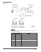
Point Database Application 6750 Point Database Application 6750 Object Type Object Instance (Point Number) Object Name (Descriptor) Factory Default (SI Units) Eng Units (SI Units) Range Active Text Inactive Text AO 1 CTLR ADDRESS 255 -- 0-255 -- -- AO 2 APPLICATION 6792 -- 0-32767 -- -- AO 3 TEMP OFFSET 0.0 (0.0) DEG F (DEG C) -31.75-32 -- -- AI {04} ROOM TEMP 74.0 (23.44888) DEG F (DEG C) 48-111.75 -- -- AO 5 OCC DIF STPT 400 (188.
Point Database Application 6750 Object Type Object Instance (Point Number) Object Name (Descriptor) Factory Default (SI Units) Eng Units (SI Units) Range Active Text Inactive Text BO {29} NET OCC CMD OCC -- Binary UNOCC OCC AI {30} GEX AIR VOL 0 (0.0) CFM (LPS) 0-32764 -- -- AO {31} OCC SUP MAX 3400 (1604.46) CFM (LPS) 0-32764 -- -- AO {32} OCC SUP MIN 340 (160.446) CFM (LPS) 0-32764 -- -- AO {33} OCC GEX MAX 1100 (519.
Point Database Application 6750 Object Type Object Instance (Point Number) Object Name (Descriptor) Factory Default (SI Units) Eng Units (SI Units) Range Active Text Inactive Text AO {61} OTHER SUP 0 (0.0) CFM (LPS) 0-16380 -- -- BO {62} CAL SUP VLV NO -- Binary YES NO AO 65 ROOM P GAIN 20.0 (36.0) -- 0-8191.75 -- -- AO 66 ROOM I GAIN 0.01 (0.018) -- 0-32.767 -- -- AO {67} UOC GEX MAX 1000 (471.9) CFM (LPS) 0-32764 -- -- AO {68} UOC GEX MIN 500 (235.
Point Database Application 6750 Object Type Object Instance (Point Number) Object Name (Descriptor) Factory Default (SI Units) Eng Units (SI Units) Range Active Text Inactive Text BO {92} VENT ALM OFF -- Binary ON OFF AO {93} SUP FLO STPT 0 (0.0) CFM (LPS) 0-16380 -- -- BO {94} CAL AIR NO -- Binary YES NO AO 95 CAL SETUP 4 -- 0-255 -- -- AO 96 CAL TIMER 12 HRS 0-255 -- -- AO 97 SUPDUCT AREA 1.0 (0.09292) SQ. FT (SQ M) 0-6.
Point Database (Slave Mode) Application 6792 Point Database (Slave Mode) Application 6792 Object Type Object Instance (Point Number) Object Name (Descriptor) Factory Default (SI Units) Eng Units (SI Units) Range Active Text Inactive Text AO 1 CTLR ADDRESS 255 -- 0-255 -- -- AO 2 APPLICATION 6792 -- 0-32767 -- -- AO 3 TEMP OFFSET 0.0 (0.0) DEG F (DEG C) -31.75-32 -- -- AI {04} ROOM TEMP 74.0 (23.44888) DEG F (DEG C) 48-111.75 -- -- AI {13} ROOM STPT 74.0 (23.
Point Database (Slave Mode) Application 6792 Object Type Object Instance (Point Number) Object Name (Descriptor) Factory Default (SI Units) Eng Units (SI Units) Range Active Text Inactive Text AI {84} AI 5 74.0 (23.496) DEG F (DEG C) 37.5-165 -- -- BO {94} CAL AIR NO -- Binary YES NO AO 95 CAL SETUP 4 -- 0-255 -- -- AO 96 CAL TIMER 12 HRS 0-255 -- -- AO 97 DUCT AREA 1 1.0 (0.09292) SQ. FT (SQ M) 0-6.
Issued by Siemens Industry, Inc. Building Technologies Division 1000 Deerfield Pkwy Buffalo Grove IL 60089 Tel. +1 847-215-1000 Document ID 140-1328 Edition 2015-07-07 © Siemens Industry, Inc., 2015 Technical specifications and availability subject to change without notice.