
Application

Sequence of Operation
Airflow Control
25
Siemens Industry, Inc.
Application Note, App 6750
140-1328
2015-07-07
Airflow Control
Both supply flow and general exhaust flow are controlled as follows:
An embedded table statement works together with a feedback loop to operate the
Venturi Air Valve (either supply or general exhaust) so that the measured air velocity is
maintained at setpoint.
In these applications, the supply and general exhaust Venturi Air Valves can operate in
one of three modes:
Mode 1 – Operates with both a PID loop and a Venturi table.
This mode provides the best control and would be the most commonly used mode
for these applications. In this mode, the embedded Venturi table statements works
together with a PID feedback loop to operate the Venturi air valve so that the
measured air velocity is maintained at setpoint. The following several sections
describe this mode.
Mode 2 - Operates with a PID loop, but no Venturi table.
In this mode, the controller operates with PID control based on a flow sensor input,
but the Venturi table is not used. See the
PID Only Mode
section later in this
document for specific information on this mode.
Mode 3 - Operates with Venturi table, but no PID loop
In this mode, the controller operates open loop (without a flow sensor). There is no
PID control. Positioning of the actuator is based solely on a Venturi table consisting
of command voltages and their resultant corresponding airflows. See the
Open
Loop Mode
section later in this document for specific information on how this mode
differs from the normal Mode 1 above.
Feedback Loop Operation
When the flow is slightly below the setpoint, the controller opens the Venturi Air Valve
slowly, more and more until the airflow reaches the setpoint, at which time the air
valve’s position remains constant. If the flow is far below the setpoint, the controller
opens the Venturi Air Valve rapidly, and rapidly increases until the airflow reaches the
setpoint, at which time the air valve’s position remains constant. The feedback gains
SUP P GAIN and GEX P GAIN are adjusted to tune the flow loops. The sample loop
time for the flow loops is fixed at 0.2 seconds. I and D gain are inherent in the system
and do not need adjustment.
NOTES:
1. Open the door to the controlled space and set VOL DIF STPT must be set to 0
while the flow loops are being tuned.
2. The Venturi Air Valve command points, SUP DMPR AO2 and GEX DMPR AO3,
indicate Venturi Air Valve position. Each Venturi Air Valve may be set up for normally
open or normally closed operation.
3. Adjusting P gains (supply and/or exhaust) to values greater than 0.1 may cause
system instability.
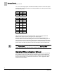
Table Statement and Feedback Loop Interaction
Supply Air Velocity Control
A table statement and the supply air velocity feedback control loop work together to
control the supply air velocity. (The table statement values are generated automatically
during calibration of the supply Venturi Air Valve.) The table statement and the control
loop work together as follows: