
Installation Instructions

Installation Instructions
Document No. 546-00335
December 8, 2011
Laboratory Exhaust Air Terminal
Item Number 546-00335, Rev. EA Page 1 of 5
Product Description
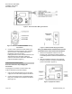
The Laboratory Exhaust Terminal (LGE) is a one-
piece flow control device used to vary airflow
through an exhaust duct. See Figure 1 and Figure 2.
The terminal consists of a duct section, flow sensor,
and a damper blade.
NOTE: The terminal’s 90° damper does not have a
gasket seal.
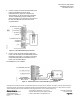
Figure 1. Slip Ends Exhaust Terminal.
Figure 2. Flanged Ends Exhaust Terminal.
Options
• Sizes 4", 6", 7”, 8", 9”, 10", 11”, 12", 14", 16",
18”
• Galvanized/90, without seal; 316L stainless
steel/90, without seal
• Slip or flange end fittings
• 316L Stainless steel and Teflon™ coated
construction:
• Solid stainless steel shaft on Teflon
bearings
• Orifice plate SP300
• Galvanized Construction:
• 1/2-inch (1.276 m) zinc plated shaft
• Orifice plate or SP300 airflow
measurement sensor
Product Numbers
Contact your Siemens Industry, Inc. representative
for detailed parts information.
Warning Notation
WARNING
Personal injury/loss of life may
occur if you do not follow a
procedure as specified.
Electronic Actuation
• Control packages including an Electronic
Actuator assembly with mounting bracket,
and a differential pressure transmitter
(optional). These parts are included in an
enclosure that is factory-mounted to the
outside of the terminal.
Pneumatic Actuation
• Control packages including one or all of the
following: Analog Output–Pneumatic (AO–P)
Transducers, No. 3 pneumatic actuator, and
one differential pressure transmitter
(optional). These parts can be included in an
optional enclosure that is factory-mounted to
the outside of the terminal.
Required Tools
• Small flat blade screwdriver
• 3/8-inch open end wrench
• Needle nose pliers
• Duct tape
• Sealant
• Sheet metal screws
• 1/4-inch poly tubing