
Installation Instructions

Document No. 546-00335
Installation Instructions
December 8, 2011
Page 2 of 5 Siemens Industry, Inc.
Expected Installation Time
30 minutes
Prerequisites
• Terminal ductwork free of debris
• Construction filters in place
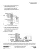
• One duct diameter of rigid straight ductwork
upstream of terminal. See Figure 3.
• Air lines installed (for pneumatic applications)
• Exhaust ductwork installed
NOTE: Terminals should be located so that they do
not come in contact with rigid conduit,
sprinkler piping, Greenfield metal covering,
or rigid pneumatic tubing. Do not install
terminals tight against concrete slabs or
columns because vibrations are amplified
through these structures. Also, allow
clearance for service access to controls.
Instructions
Installation instructions for the LGEs are presented
in the following two sections:
1. Section 1 applies to mounting the terminal
unit.
2. Section 2 applies to actuation.
Section 1 – Mounting
1. Move the terminal to the installation area.
Remove the terminal from the shipping package.
Do not carry the terminal by the orifice sensor.
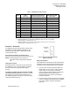
Terminal measurements are included in Table 1.
2. Connect the exhaust ductwork to the exhaust
terminal’s inlet collar using the accepted trade
practice of welding or bolting the exhaust
terminal to the ductwork.
3. Connect the exhaust ductwork to the exhaust
terminal’s outlet collar using the accepted trade
practice of welding or bolting the exhaust
terminal to the ductwork.
4. Seal all ductwork and check that the exhaust
duct connections are airtight.
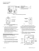
Figure 3. Exhaust Terminal Properly Installed
after an Elbow Duct Section.
NOTE: Always mount the equipment enclosure
on the side of the duct (vertically)
(Figure 4). Mounting the equipment
enclosure on the top or bottom of the
duct (horizontally) will adversely affect
the measurement accuracy.
Figure 4. FHET Installed Properly.