
Installation Instructions

Document No. 546-00335
Installation Instructions
December 8, 2011
Siemens Industry, Inc.
Page 3 of 5
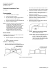
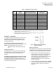
Table 1. LGE Dimensions by Unit Size.
Duct
Size
Length (L) Inches
(mm)
+
0.06 (1.5)
Slip End Outside Diameter
(OD) or Flange End Inside
Diameter (ID) Inches (mm)
Flange
Bolt Hole Circle Size
Inches (mm)
4 16.00 (406.4) 3.88 (98.6) 5.25 (133.4)
6 16.00 (406.4) 5.88 (149.4) 7.25 (184.2)
7 16.00 (406.4) 6.88 (174.8) 8.25 (209.6)
8 16.00 (406.4) 7.88 (200.2) 9.25 (234.95)
9 19.50 (495.3) 8.88 (225.6) 10.25 (260.4)
10 19.50 (495.3) 9.88 (251.0) 11.25 (285.8)
11 20.50 (520.7) 11.88 (301.8) 13.25 (336.6)
12 20.50 (520.7) 11.88 (301.8) 13.25 (336.6)
14 23.00 (584.2) 13.88 (352.6) 15.75 (400.1)
16 25.00 (635.0) 15.88 (403.4) 17.75 (450.9)
18 25.001 (635.0) 17.88 (454.2) 19.75 (501.7)
1. Provide a minimum of 1 duct diameters of straight rigid duct directly upstream.
2. Flanged connection is 1.0” (25.4 mm) for 4” through 10” sizes. OD = OD + 2.0” (50.8 mm).
Bolt hole quantity = 6, Bolt hole size = 0.375”.
3. Flanged connection is 1.5” (38.1 mm) for 11” through 16” sizes. OD = OD + 3.0” (76.2 mm).
Bolt hole quantity = 8, Bolt hole size = 0.4375”.
Section 2 – Actuation
For application specific actuator wiring, reference the
appropriate controller installation instructions. For
actuator wiring, reference the appropriate actuator
Technical Instructions.
Field Panels and Unitary Controllers (UCs)
NOTE: For field panels and UCs, the AO–P
Transducer used in these steps is P/N 545-
113.
Tubing Connections
Several pneumatic connections must be made from
the field panel or UC to the terminal box to operate
the AO-P Transducer and pneumatic damper
actuator.
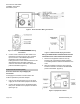
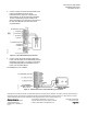
For damper, actuator and valve controls mounted
inside the controls enclosure. Connect the 1/4-inch
poly tubing from the 20 to 30 psi supply line to the
port labeled “Supply Air 20–30 psi” on the side of the
controls enclosure (Figure 5).
Figure 5. Exhaust Terminal Pneumatic
Piping Connections.
Wiring Connections
Several electrical connections must be made from the
field panel or UC to the terminal to operate the AO-P
Transducer and the differential pressure transmitter.
3. Connect a two-conductor 20 AWG cable to the
Field Panel’s 0 to 10V output or UC’s universal
output. Connect it to the AO–P Transducer
connected to the exhaust damper or through the
wiring bushing/knockout on the terminal
enclosure (Figure 5) to the AO–P Transducer
inside the enclosure.
4. The wire bushing can be removed and a standard
1/2-inch conduit knockout fitting may be installed.
Connect the cable to the AO–P Transducer
(Figure 6).