
Installation Instructions

Document No. 546-00335
Installation Instructions
December 8, 2011
Page 4 of 5 Siemens Industry, Inc.
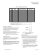
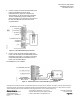
Figure 6. AO-P Transducer Wiring Connections.
Figure 7. Differential Pressure Transmitter Wiring
Connections.
5. Connect a two-conductor 20 AWG cable to the
field panel’s 4 to 20 mA input or UC’s universal
input. Connect it to the differential pressure
transmitter or through the wiring
bushing/knockout on the controls enclosure to the
differential pressure transmitter inside the
enclosure. Connect the cable to the differential
pressure transmitter (Figure 7).
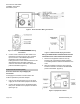
Fume Hood Controllers (FHCs)
Provision of the 18 to 30 psi Supply Air
Connection
One supply air connection must be made to the
FHET to operate the pneumatic damper.
1. Use 1/4-inch OD poly tubing for an 18 to 30 psi
supply air line to the FHET equipment enclosure.
2. Connect the supply air line to the barbed supply
inlet port on the side of the equipment enclosure
(See Figure 8).
Figure 8. FHET Pneumatic Piping Connection.
Wiring the AO-P Module and Differential Pressure
Transmitter to the Fume Hood Controller Board.
1. Remove the equipment enclosure cover by
loosening the quick release butterfly fasteners.
The butterfly fasteners will remain attached to the
cover.
2. With the equipment enclosure cover removed,
locate the Lab AO-P module and the differential
pressure transmitter. (Figure 9).
Figure 9. Equipment Locations.