
Installation Instructions

Document No. 546-00335
Installation Instructions
December 8, 2011
Information in this document is based on specifications believed correct at the time of publication. The right is reserved to make changes as
design improvements are introduced. APOGEE and Insight are registered trademarks of Siemens Industry, Inc. Other product or company
names mentioned herein may be the trademarks of their respective owners. © 2011 Siemens Industry, Inc.
Siemens Industry, Inc.
Building Technologies Division
1000 Deerfield Parkway
Buffalo Grove, IL 60089-4513
U.S.A
Your feedback is important to us. If you have
comments about this document, please send them
to SBT_technical.editor.us.sbt@siemens.com.
Document No.546-00335
Printed in the USA
Page 5 of 5
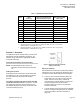
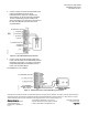
3. Connect a three conductor 20 AWG cable for the
Lab AO-P Module through the wiring
bushing/knockout. (Figure 9). If desired, the
wiring bushing can be removed and a standard
1/2-inch conduit fitting may be installed in its
place. See Figure 10 for the wiring connections to
the Lab AO-P Module from the Fume Hood
Controller Board.
Figure 10. AO-P Module Wiring Connections.
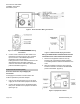
4. Connect a two conductor 20 AWG cable to the
Fume Hood Controller for the differential pressure
transmitter. See Figure 11 for wiring connections
to the differential pressure transmitter from the
Fume Hood Controller Board.
The installation is now complete.
Figure 11. Differential Pressure Transmitter Wiring Connections