BACnet LCM-OAVS Room Pressurization with Slowacting Damper Actuation (One Exhaust, One Supply) and Hot Water Reheat, Application 6753 Application Note 140-1334 2015-07-07 Building Technologies
Table of Contents Overview ............................................................................................................................. 5 BACnet .............................................................................................................................. 6 Auto Discovery ..................................................................................................................... 7 Auto Addressing ......................................................................
Local Annunciation ............................................................................................. 24 Network Annunciation......................................................................................... 25 Damper Position on Return from Power Failure ................................................................ 25 Operation of AVS FAILMODE ........................................................................................... 26 Fail Mode Operation .............................
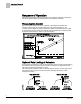
Sequence of Operation BACnet Overview Application 6753 controls pressurization, ventilation, and room temperature in a laboratory room served by one single-duct supply terminal with a reheat coil, one general exhaust terminal, and up to six fume hoods (multiple fume hood flow signals must be averaged using an averaging and scaling module. Pressurization is controlled by maintaining a selected difference between supply and exhaust airflows.
Sequence of Operation BACnet Ventilation and Pressurization Control Drawing. BACnet The controller communicates using BACnet MS/TP protocol for open communications on BACnet MS/TP networks.
Sequence of Operation Auto Discovery Auto Discovery Auto Discovery allows you to automatically discover and identify PTEC/ATEC controllers on the BACnet MS/TP Network. There are two basic configurations: Devices not configured with an address. (Devices are discovered by their unique serial number.) Devices configured with an address and available for modification. Auto Addressing Auto Addressing allows you to automatically assign device addresses to a PTEC/ATEC controller on the BACnet MS/TP Network.
Sequence of Operation Pressurization Control Sequence of Operation The following paragraphs present the sequence of operation for BACnet LCM-OAVS VAV Room Pressurization with HW Reheat and Slow Damper Actuation. Pressurization Control The goal of pressurization control is to maintain a fixed difference between the volumes of total supply air and total exhaust air (see the following figure).
Sequence of Operation Room Airflow Balance To deal with the possibility of unequal flow rate changes, the application includes two new points which allow field adjustment to slow down actuators. SUP MAX RATE effectively limits the speed of the supply actuator; GEX MAX RATE effectively limits the speed of the exhaust actuator. SUP MAX RATE and GEX MAX RATE should be changed to values other than 0 only after a thorough analysis has been made of the job specific scenarios.
Sequence of Operation Occupancy NOTE: VOL DIFFRNC and VOL DIF STPT are positive numbers in a room that is negatively pressurized and negative in a positively pressurized room. Application 6753 has the ability to maintain a different volume differential setpoint during occupied mode than during unoccupied mode. When OCC.UNOCC = OCC, VOL DIF STPT = OCC DIF STPT. When OCC.UNOCC = UNOCC, VOL DIF STPT = UOC DIF STPT.
Sequence of Operation Active Flow Minimums and Maximums The following table shows what is enabled when OCC ENA is at a particular value. OCC ENA Values. OCC ENA (value) 0 (default) Description Both OCC BUTN DI1 and OCC SWIT DI2 are disabled. 1 Only OCC BUTN DI1 is enabled. 2 Only OCC SWIT DI2 is enabled. NOTE: OCC ENA does not allow both OCC BUTN DI1 and OCC SWIT DI2 to be enabled at the same time. If OCC ENA is set greater than 2, it will default to 0.
Sequence of Operation VAV versus CV Control VAV versus CV Control In Application 6753, VAV means that the supply airflow can be varied to provide cooling. CV means the supply airflow is not a source of cooling. However, the supply and general exhaust can still change in CV mode to keep the volume differential setpoint constant. This may be necessary if HOOD VOL is varying. Application 6753 can do either Variable Air Volume control (VAV) or Constant Air Volume Control (CV).
Sequence of Operation Flow Tracking – Supply Tracks Exhaust vs. Exhaust Tracks Supply NOTE: If desired, the LCM can be used without any fume hoods attached. In this case, MAX HOOD VOL should be set to 0 cfm to disable the alarming that would occur if the fume hood flow input drops below 1 Vdc. Flow Tracking – Supply Tracks Exhaust vs.
Sequence of Operation Calculating Exhaust Flow Setpoint TRACK METHOD TRACK METHOD is a point associated with TRACK MODE. TRACK MODE determines which airflow (supply or general exhaust) gets tracked and which airflow does the tracking. TRACK METHOD determines how tracking is accomplished. If TRACK MODE is set to ETS and TRACK METHOD is set for FLOW tracking, the general exhaust flow setpoint is calculated according to the measured value, SUP AIR VOL.
Sequence of Operation Calculating Supply Flow Setpoint When Exhaust Tracks Supply (ETS) flow tracking is used, the general exhaust airflow setpoint is calculated the same during both VAV and CV operation, as follows: To calculate GEX FLO STPT, the controller determines the general exhaust airflow value that pressurizes the room based on the values of VOL DIF STPT, OTHER EXH, OTHER SUP and either SUP FLO STPT or SUP AIR VOL depending on the value of TRACK METHOD.
Sequence of Operation Ventilation – VAV Mode Ventilation – VAV Mode During VAV operation, the ventilation works as follows: OCC SUP MIN, the occupied supply minimum, is used to ensure that the room receives enough supply air for proper ventilation during the occupied mode. UOC SUP MIN is used to ensure that the room receives enough supply air for proper ventilation during the unoccupied mode.
Sequence of Operation Airflow Control When calibration is in progress, CAL AIR equals YES. After calibration, CAL AIR returns to NO. The application uses Autozero Modules connected to AUTOZERO DO8. This means that the supply and general exhaust flow control devices do not close during calibration of the transducers. NOTE: The LCM does not monitor Fume Hood flow changes for 3 seconds during AVS calibration.
Sequence of Operation Operating Without a Supply or Exhaust Operating Without a Supply or Exhaust It is possible to run this application without the supply or exhaust if the corresponding flow coefficient is set to zero. When the flow coefficient is zero and the offboard air module is not connected the air velocity sensor will not display a FAIL status and the flow loop will be allowed to run with a flow value of zero. See the Application Notes section for more information.
Sequence of Operation Room Temperature Offset If ROOM STPT is less than RM STPT MIN, then CTL STPT is set equal to RM STPT MIN. If ROOM STPT is less than or equal to RM STPT MAX and greater than or equal to RM STPT MIN, then CTL STPT is set equal to ROOM STPT. If CTL STPT is overridden or being controlled by a field panel, then RM STPT MIN and/or RM STPT MAX have no effect on CTL STPT. The application also uses CTL TEMP as the temperature input for the Room Temperature PID Loop.
Sequence of Operation Room Unit Operation Room Unit Operation Sensor Select SENSOR SEL is a configurable, enumerated point (values are additive). This point tells the controller what type of room unit is being used and how to handle loss of communication, for more information see Fail Mode Operation [➙ 27]. It also provides the ability to enable the optional RH and CO2 sensors and indicates which thermistor type is connected.
Sequence of Operation PPCL STATUS Room CO2 RM CO2 displays the CO2 value in units of parts-per-million (PPM). RM CO2 (from the digital 2200/2300 room units) can be used with PPCL in the PTEC/ATEC controller or unbundled for control or monitoring purposes. Room RH RM RH displays the relative humidity value in percent. RM RH can be used for PPCL in the PTEC or unbundled for control or monitoring purposes. RM RH displays the relative humidity value in percent.
Sequence of Operation Temperature Control Loop Temperature Control Sequence. The range of TEMP LOOPOUT is 0 to 100%. Higher values indicate a need for more cooling (or less heat). The Figure Temperature Control Sequence shows that as the value of TEMP LOOPOUT moves from START to 0%, and the reheat VALVE CMD is modulated from 0 to 100%. VALVE CMD is converted to a voltage and put out on REHEAT A01.
Sequence of Operation Alarms Alarms The controller is equipped with ventilation and pressurization alarms. It does not contain temperature alarms. The controller’s alarms are designed to: Inform room occupants of hazards. Inform building operation personnel that the system is not functioning correctly. Supply data for documenting laboratory safety records through trending. These alarms can be annunciated locally and/or broadcast across a network.
Sequence of Operation Alarms Pressurization Alarm The pressurization alarm, VOL DIF ALM indicates that the difference between supply and exhaust flow is not what it should be, or that the controller can't calculate the flow difference, VOL DIFFRNC, because it has lost a flow signal. The Figure Failure Mode Sequence lists reasons why VOL DIFFRNC may fail. The pressurization alarm point is turned on when at least one of the following conditions occurs: VOL DIFFRNC has a status of Failed.
Sequence of Operation Damper Position on Return from Power Failure ALARM ENA Values. ALARM ENA 5 Vent Alarm and Dif Alarm are enabled. 6 Alarm Switch and Dif Alarm are enabled. 7 Vent Alarm, Alarm Switch, and Dif Alarm are all enabled. NOTE: If ALARM ENA is set greater than 7, it will default to 0. ALM ENA is additive. For example, if ALM ENA equals 5, then either a ventilation or a pressurization alarm will activate ALARM DO7, but the alarm switch will not.
Sequence of Operation Operation of AVS FAILMODE Reversed for rooms where negative or neutral pressurization is required and Enabled for positively pressurized rooms. The default for the Motor direction is direct (not reversed). Use the values in the followin table to determine the value for MTR SETUP. The values are additive. For example, if you want to have Motor 1 (DOs 1 and 2) enabled, Motor 2 (DOs 3 and 4) enabled and reversed, you would set MTR SETUP equal to 13.
Sequence of Operation Fail Mode Operation The last two values of AVS FAILMODE do not describe specific actions; that is, when an AVS fails, the supply and general exhaust will react differently depending on the circumstances. If AVS FAILMODE equals 7, the supply Damper will hold. The general exhaust Damper will also hold if a fume hood is present (that is, if MAX HOOD VOL > 0).
Sequence of Operation Fail Mode Operation Fume Hood Flow – If the LCM receives an invalid (less than 1 Vdc) fume hood flow signal, or the fume hood controller (FHC) loses power or loses its flow sensor, HOOD VOL will fail. If HOOD VOL fails and if VOL DIF STPT is greater than or equal to 0 (negative or neutral pressurization required), the supply and exhaust loops assume a hood exhaust value of 0 cfm and continue to maintain user-defined pressurization.
Sequence of Operation Application Notes Application Notes Supply Only - Operating Without a General Exhaust Box This application can operate without a general exhaust box. If a general exhaust box is not being controlled, set TRACK METHOD to FLOW and set the following points: TRACK MODE to 3. – Without a fume hood attached, use a value of 3 = ETS (exhaust tracks supply) Flow Tracking, should be used for both the occupied and unoccupied modes.
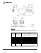
Sequence of Operation Wiring Diagrams Since all temperature control will be done by the reheat valve, START should be set to 100 to allow the reheat valve to be controlled by the full range of TEMP LOOPOUT and to prevent the room temperature PID Loop from winding up. Wiring Diagrams Offboard Air Module Wiring. CAUTION The LCM-OAVS has two terminal blocks with terminations numbered identically (terminations 1 through 16). DO NOT mix these up with each other.
Sequence of Operation Wiring Diagrams NOTE: If the voltage/current switch is set to current and a 4 to 20 mA sensor is connected to an AI, then special wiring requirements must be followed. NOTE: The controller’s DOs control 24 Vac loads only. The maximum rating is 12 VA for each DO.
Sequence of Operation Wiring Diagrams BACnet LCM-OAVS Slow Actuation Damper Supply/Damper Exhaust – Application 6753 Wiring Diagram. 32 Siemens Industry, Inc.
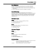
Point Database Application 6753 Point Database Application 6753 Object Type Object Instance (Point Number) Object Name (Descriptor) Factory Default (SI Units) Eng Units (SI Units) Range Active Text Inactive Text AO 1 CTLR ADDRESS 255 -- 0-255 -- -- AO 2 APPLICATION 6792 -- 0-32767 -- -- AO 3 TEMP OFFSET 0.0 (0.0) DEG F (DEG C) -31.75-32 -- -- AI {04} ROOM TEMP 74.0 (23.44888) DEG F (DEG C) 48-111.75 -- -- AO 5 OCC DIF STPT 400 (188.
Point Database Application 6753 Object Type Object Instance (Point Number) Object Name (Descriptor) Factory Default (SI Units) Eng Units (SI Units) Range Active Text Inactive Text AO {32} OCC SUP MIN 340 (160.446) CFM (LPS) 0-32764 -- -- AO {33} OCC GEX MAX 1100 (519.09) CFM (LPS) 0-32764 -- -- AO {34} OCC GEX MIN 600 (283.14) CFM (LPS) 0-32764 -- -- AI {35} SUP AIR VOL 0 (0.0) CFM (LPS) 0-32764 -- -- AO 36 SUP FLO COEF 0.73 -- 0-2.
Point Database Application 6753 Object Type Object Instance (Point Number) Object Name (Descriptor) Factory Default (SI Units) Eng Units (SI Units) Range Active Text Inactive Text (235.95) AI {69} TOTL SUPPLY 0 (0.0) CFM (LPS) 0-32764 -- -- AO 70 SUP P GAIN 0.015 -- 0-4.095 -- -- AO {71} UOC SUP MAX 2200 (1038.18) CFM (LPS) 0-32764 -- -- AO {72} UOC SUP MIN 220 (103.818) CFM (LPS) 0-32764 -- -- AO {73} CTL STPT 74.0 (23.44888) DEG F (DEG C) 48-111.
Point Database Application 6753 Object Type Object Instance (Point Number) Object Name (Descriptor) Factory Default (SI Units) Eng Units (SI Units) Range Active Text Inactive Text AO 110 MTR SETUP 0 -- 0-255 -- -- AO {111} SUP DMP POS 0 PCT 0-102 -- -- AO 112 MTR1 TIMING 95 SEC 0-511 -- -- AO 113 MTR1 ROT ANG 90 -- 0-255 -- -- AO {114} GEX DMP POS 0 PCT 0-102 -- -- AO 115 MTR2 TIMING 95 SEC 0-511 -- -- AO 116 MTR2 ROT ANG 90 -- 0-255 -- -- AO
Point Database (Slave Mode) Application 6792 Point Database (Slave Mode) Application 6792 Object Type Object Instance (Point Number) Object Name (Descriptor) Factory Default (SI Units) Eng Units (SI Units) Range Active Text Inactive Text AO 1 CTLR ADDRESS 255 -- 0-255 -- -- AO 2 APPLICATION 6792 -- 0-32767 -- -- AO 3 TEMP OFFSET 0.0 (0.0) DEG F (DEG C) -31.75-32 -- -- AI {04} ROOM TEMP 74.0 (23.44888) DEG F (DEG C) 48-111.75 -- -- AI {13} ROOM STPT 74.0 (23.
Point Database (Slave Mode) Application 6792 Object Type Object Instance (Point Number) Object Name (Descriptor) Factory Default (SI Units) Eng Units (SI Units) Range Active Text Inactive Text AI {84} AI 5 74.0 (23.496) DEG F (DEG C) 37.5-165 -- -- BO {94} CAL AIR NO -- Binary YES NO AO 95 CAL SETUP 4 -- 0-255 -- -- AO 96 CAL TIMER 12 HRS 0-255 -- -- AO 97 DUCT AREA 1 1.0 (0.09292) SQ. FT (SQ M) 0-6.
Issued by Siemens Industry, Inc. Building Technologies Division 1000 Deerfield Pkwy Buffalo Grove IL 60089 Tel. +1 847-215-1000 Document ID 140-1334 Edition 2015-07-07 © Siemens Industry, Inc., 2015 Technical specifications and availability subject to change without notice.