BACnet Programmable Fume Hood Controller Vertical Sash Configuration with Damper or Venturi Valve Application 6741 and Application 6742 Application Note Building Technologies 140-1344 2015-11-09 Restricted
Table of Contents Overview ............................................................................................................................. 4 BACnet .............................................................................................................................. 7 Auto Discovery ..................................................................................................................... 7 Auto Addressing ......................................................................
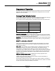
Overview BACnet Overview Application 6741 and Application 6742 are designed for use with a wide range of fume hood sash configurations connected to a manifold fume hood exhaust system. The sash configurations include: Bench style fume hoods – single vertical sash Dual Bench style fume hoods – side-by-side single vertical sash Floor Mounted style fume hoods – two vertical sashes, one on top of the other WARNING The application cannot detect a broken wire to the analog input for the second sash.
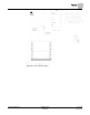
Overview BACnet Application 6741 Control Drawing. 5 Siemens Industry, Inc.
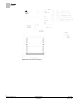
Overview BACnet Application 6742 Control Drawing. 6 Siemens Industry, Inc.
Overview BACnet BACnet The controller communicates using BACnet MS/TP protocol for open communications on BACnet MS/TP networks.
Overview Hardware Inputs Hardware Inputs Analog Air velocity sensor(s) – (2nd sensor available for field use) (Optional) Differential pressure transmitter/Linear Flow input (Vortex Shedder) (Optional) External face area Vertical sash sensor(s) Digital Operator Display Panel (ODP) ATTN.UNATTN (through DI 2) OCC.
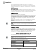
Sequence of Operation Average Face Velocity Control Sequence of Operation The following paragraphs present the sequence of operation for Fume Hood Controller Application 6741 and Application 6742: Vertical Sash Configuration Fume Hood with Damper or Venturi Air Valve. Average Face Velocity Control In face velocity mode, the Fume Hood Controller maintains the average face velocity at the face velocity setpoint, FVEL STPT.
Sequence of Operation AVS Calibration If the face velocity setpoint is overridden by the system or the controller is in Emergency/General Failure this function does not work. The controller will remember the current occupied face velocity setpoint even after changing from unoccupied back to occupied. Air Velocity Sensing Primary sensing of the exhaust airflow is through the OAVS. Optionally, AI3 may be used to input a Differential pressure transmitter or a Linear Flow input signal.
Sequence of Operation AO2 Flow Signal AO2 DEADBAND defaults to 5.2%. If EXH STPT is 1000 cfm, AO2 FLOW SIG = EXH STPT if the actual flow is between 948 and 1052 cfm (these values are approximate and will vary based on duct area). If the actual flow is outside these values AO2 FLOW SIG = EXH VOL. For stable pressure reading, lower the AO2 DEADBAND. For unstable pressure readings, raise the AO2 DEADBAND until the output signal stabilizes. AO2 DEADBAND can be set from 0 to 102% in 0.4 % increments.
Sequence of Operation Control Loop - Damper Application Control Loop - Damper Application The PID loop controls the damper based on the values of EXH VOL and EXH STPT. The loop output, DMPR CMD, controls EXTN DO1 and RETC DO2 through a time modulation scheme. The DMPR CMD ranges of -100 to 100%. -100% is the maximum extend which closes the damper at full speed. 0% holds the damper at its current position. 100% is the maximum retract which opens the damper at full speed.
Sequence of Operation Venturi Application The exhaust Venturi Air Valve is calibrated by setting CAL EXH VLV to YES. Calibration proceeds automatically and takes about 3 minutes, after which CAL EXH VLV returns to NO. If calibration is successful, EXH VLV STAT is set to CAL OK. A failed calibration requires checking the equipment for possible causes—loose or kinked flow sensor tubes, improper actuator or valve operation, etc.—followed by recalibration.
Sequence of Operation Venturi Application Table Venturi Table Statement Example shows an example of active values in a Venturi table statement after the Venturi Air Valves have been calibrated (note reverse acting exhaust voltage). Table statement values will vary per system. Venturi Table Statement Example (active values). Exhaust Venturi Air Valve a) cfm volts 0 a) 10 a) 180 5.48 216 5.08 244 4.68 340 3.88 368 3.48 452 2.98 476 2.73 504 2.48 572 1.98 604 1.73 618 1.48 712 0.
Sequence of Operation Venturi Application NOTE: The first pair (or “point”) of flow/voltage values in the table statement is the low flow point. It is provided for low flow situations where airflow through the Venturi Air Valve must be controlled at velocities less than 350 fpm. Otherwise, this point can be left at factory default of 0 cfm and 0V (10V if exhaust) and ignored, as is the case in the example table statement in Table Venturi Table Statement Example.
Sequence of Operation Venturi Application Problematic Venturi Air Valve Voltage/Flow Curves. NOTE: Bouncy flow means that airflow through the air valve’s flow orifice is too turbulent to be read consistently. Venturi Table Evaluation and Editing (Mode 1, 3) A Venturi Air Valve table statement consists of two sets of voltage/flow values—one set is active and the other inactive.
Sequence of Operation Venturi Application 2. Edit the inactive table values. Since you have just switched the active and inactive portions of the table in Step 1, the inactive values are now identical to what the active values were moments ago. You can now edit these new inactive values by using V TABLE PT to reference them in TABLE FLOW and TABLE VOLTS. Table Venturi Air Valve Table Statement explains this in more detail. 3. Set V TABLE PT once again to the swap value.
Sequence of Operation Venturi Application The following table lists all values for V TABLE PT and describes their use. Venturi Air Valve Table Statement V TABLE PT Description 0 Default value for V TABLE PT. When V TABLE PT equals 0, changes to TABLE FLOW or TABLE VOLTS are ignored. Setting V TABLE PT to 0 cancels an edit session.
Sequence of Operation Venturi Application PID Only (Mode 2) NOTE: The default P gain value is intended for PID operation in conjunction with the Venturi table. The P gain and Venturi table work together to provide an appropriate response to setpoint changes. When operating without the Venturi table in PID Only mode, the application is slower to respond. Therefore, you should adjust the P gain as needed when operating in PID Only mode to ensure acceptable performance.
Sequence of Operation Minimum Exhaust Mode If specific information about the voltage at low flow is known, that would be entered into point 1 which is reserved for information about low flow. See Example 2. Point Flow Volt 1 300 7.0 2 0 10.0 3 0 10.0 15 0 10.0 16 1200 0.0 Example 2 - Table with Voltage End Limits and Low Flow Value You can also manually populate the table with additional values as shown in Example 3 below.
Sequence of Operation Maximum Exhaust Mode The Fume Hood Controller maintains a constant face velocity until the minimum flow condition occurs. At that point the controller controls to a constant exhaust volume, EXH MIN. In the minimum flow mode, the face velocity rises above the desired setpoint as the open sash area decreases toward the fully closed position. This is not considered an alarm condition; no face velocity alarms will occur and flow alarms are still active. Exhaust Control Schedule.
Sequence of Operation Alarm Limits Warning and Alarm Schedule. Alarm Limits The Fume Hood Controller contains high and low flow alarm limits, HI ALM LMT and LOW ALM LMT, respectively. The alarm limits are defined as a percentage of the controller setpoint; therefore, the alarm limits apply to EXH STPT during normal control. For either of the alarms to become active, the alarm condition must be maintained for the time specified in ALARM TIME.
Sequence of Operation Table Access Feature Sash area alarms alert you when the sash area is above set limits. There are limits for both attended and unattended modes of operation. The controller uses the following points to perform this function: DI2, ATTN.UNATTN, SASH TONE, UN ALRT AREA, AT ALRT AREA, OPEN TIME, and SASH OP ALRT. ATTN.UNATTN is controlled by DI2, and when the DI is opened the controller changes to ATTN mode. When the DI is shorted, the controller changes to UNATTN mode.
Sequence of Operation Start-up/Decommission Mode Emergency Purge Schedule. NOTE: Norm = Normal operation in which control is at the EXH STPT. EMER STPT = EXH STPT increased by the value (%) of EMER STPT. MAX = Maximum flow, where the damper is controlled to fully opened. Start-up/Decommission Mode The Fume Hood Controller contains different modes controlled by STARTUP MODE (default is 3). These modes of operation allow the controller to be started up without the sound of nuisance alarms at the hood.
Sequence of Operation Fail Mode The digital output DO6 can be used for local indication that the sash was opened after the hood entered Out of Service mode. The output will remain ON until STARTUP MODE is changed. Fail Mode If the Fume Hood Controller or one of its accessories fails, then a failure mode sequence is initiated. Fume Hood Controller – If the Fume Hood Controller power fails, the exhaust damper goes to the fully opened position.
Sequence of Operation Wiring Diagrams Wiring Diagrams Offboard Air Module Wiring. CAUTION The FHC-OAVS has two terminal blocks with terminations numbered identically (terminations 1 through 16). DO NOT mix these up with each other. If the FHC-OAVS is not connected as shown, it is not resistant to electrical surges. It is also susceptible to interference from other equipment. CAUTION A separate power supply is required if a 4-20 mA sensor is used.
Sequence of Operation Wiring Diagrams Wiring for AI4: Sash Sensor 2. WARNING The application cannot detect a broken wire to the analog input for the second sash. An external sash aggregating device should be used to calculate the face area for all fume hoods with more than one sash. WARNING Must use external 10 Vdc power supply. Do not power AI from an onboard AO that is forced to 10 volts. Wiring for AI with a 4 to 20 mA Sensor. 27 Siemens Industry, Inc.
Sequence of Operation Wiring Diagrams CAUTION Each 4-20 mA sensor requires a SEPARATE dedicated power limited 24 Vdc power supply. DO NOT use the same transformer to power both the sensor and the controller. NOTE: If the voltage/current switch is set to current and a 4 to 20 mA sensor is connected to an AI, then special wiring requirements must be followed. NOTE: The controller’s DOs control 24 Vac loads only. The maximum rating is 12 VA for each DO.
Sequence of Operation Wiring Diagrams Application 6741 Wiring Diagram. 29 Siemens Industry, Inc.
Sequence of Operation Wiring Diagrams Application 6742 Wiring Diagram. 30 Siemens Industry, Inc.
Point Database Application 6741 Point Database Application 6741 Object Type Object Instance (Point Number) a) Object Name (Descriptor) Factory Default (SI Units) c) Eng Units (SI Units) c) Range Active Text Inactive Text AO 1 CTLR ADDRESS 99 -- 0-255 -- -- AO 2 APPLICATION 6700 -- 0-32767 -- -- AO {04} FACE VEL 0 (0.
Point Database Application 6741 Object Type Object Instance (Point Number) a) Object Name (Descriptor) Factory Default (SI Units) c) Eng Units (SI Units) c) Range Active Text Inactive Text AO 34 TRANS RANGE 0.0 (0.0) IN H2O (K PA) 0-3.2767 -- -- AO 35 LINEAR FL RG 0 (0.0) CFM (LPS) 0-32764 -- -- AI {36} AVS2 PRESS 0.0 (0.0) IN H2O (K PA) 0-3.2767 -- -- BI {37} DI 2 OFF -- Binary ON OFF BI {38} DI 6 OFF -- Binary ON OFF AO {39} AO 1 0 VOLTS 0-10.
Point Database Application 6741 Object Type Object Instance (Point Number) a) Object Name (Descriptor) Factory Default (SI Units) c) Eng Units (SI Units) c) Range Active Text Inactive Text AO 68 VSASH HGHT2 0.0 (0.0) INCHES (CM) 0-255.5 -- -- AO 69 TRACK HEIGHT 0.0 (0.0) INCHES (CM) 0-255.5 -- -- AO 70 BYPASS HGHT 0.0 (0.0) INCHES (CM) 0-255.5 -- -- AO {71} BYPASS OPEN 100 PCT 0-255 -- -- AO 72 FAIL AREA 0.0 (0.0) SQ. FT (SQ M) 0113.
Point Database Application 6741 Object Type Object Instance (Point Number) a) Object Name (Descriptor) Factory Default (SI Units) c) Eng Units (SI Units) c) Range Active Text Inactive Text AO 122 LO LIMIT 1 -- 0-2.55 -- -- BO 123 EMER DI6 OFF -- Binary ON OFF AO {126} AVE FACE VEL 0 (0.0) FPM (MPS) 0-4095 -- -- BO {127} PPCL STATE EMPTY -- Binary LOADED EMPTY b) a) Points not listed are not used in this application.
Point Database Application 6742 Point Database Application 6742 Object Type Object Instance (Point Number) a) Object Name (Descriptor) Factory Default Eng Units (SI Units) c) (SI Units) c) Range Active Text Inactive Text AO 1 CTLR ADDRESS 99 -- 0-255 -- -- AO 2 APPLICATION 6700 -- 0-32767 -- -- AO {04} FACE VEL 0 (0.
Point Database Application 6742 Object Type Object Instance (Point Number) a) Object Name (Descriptor) Factory Default Eng Units (SI Units) c) (SI Units) c) Range Active Text Inactive Text AO 34 TRANS RANGE 0.0 (0.0) IN H2O (K PA) 0-3.2767 -- -- AO 35 LINEAR FL RG 0 (0.0) CFM (LPS) 0-32764 -- -- AI {36} AVS2 PRESS 0.0 (0.0) IN H2O (K PA) 0-3.2767 -- -- BI {37} DI 2 OFF -- Binary ON OFF BI {38} DI 6 OFF -- Binary ON OFF AO {39} AO 1 0 VOLTS 0-10.
Point Database Application 6742 Object Type Object Instance (Point Number) a) Object Name (Descriptor) Factory Default Eng Units (SI Units) c) (SI Units) c) Range Active Text Inactive Text b) (CM) AO 66 VERT WIDTH2 0.0 (0.0) INCHES (CM) 0-255.5 -- -- AO 67 VSASH HGHT1 0.0 (0.0) INCHES (CM) 0-255.5 -- -- AO 68 VSASH HGHT2 0.0 (0.0) INCHES (CM) 0-255.5 -- -- AO 69 TRACK HEIGHT 0.0 (0.0) INCHES (CM) 0-255.5 -- -- AO 70 BYPASS HGHT 0.0 (0.0) INCHES (CM) 0-255.
Point Database Application 6742 Object Type Object Instance (Point Number) a) Object Name (Descriptor) Factory Default Eng Units (SI Units) c) (SI Units) c) Range Active Text Inactive Text AO 95 CAL SETUP 4 -- 0-255 -- -- AO 96 CAL TIMER 12 HRS 0-255 -- -- AI {97} AVS1 PRESS 0.0 (0.0) IN H2O (K PA) 0-3.2767 -- -- AO 98 LOOP TIME 0.1 SEC 0-25.5 -- -- AO {99} ERROR STATUS 0 -- 0-255 -- -- AO 106 DISPLAY WT 100 PCT 0-102 -- -- AO 107 DISPLAY RES 5 (0.
Issued by Siemens Industry, Inc. Building Technologies Division 1000 Deerfield Pkwy Buffalo Grove IL 60089 Tel. +1 847-215-1000 Document ID 140-1344 Edition 2015-11-09 © Siemens Industry, Inc., 2015 Technical specifications and availability subject to change without notice.