
Basic Documentation
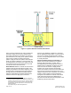
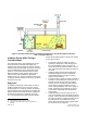
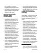
Table Of Contents
- Industry Guidelines and Preventing the Spread of Disease
- Preventing the Spread of Disease in Healthcare Facilities
- Disease Transmission
- Design Requirements for Healthcare Facilities
- Isolation Room HVAC Design Considerations
- General Healthcare Facility Ventilation Related Recommendations
- Construction and Renovation Procedures
- Commissioning

the components of the immune system that are most
severely affected. Conditions associated with
immunocompromise may be congenital or acquired
(for example, genetically determined primary
immune deficiencies, human immunodeficiency virus
infection). Immunocompromised states also make it
more difficult to diagnose certain infections (for
example, tuberculosis) and are associated with more
severe clinical disease states than those seen in
persons with a normal immune system.
10
Most
notably this includes patients who are suffering from
extensive burns, leukemia, are recovering from bone
marrow and organ transplant surgery. .
Protective Environment Room Layout–Figure 3
sho
ws a diagram of the preferred room arrangement
and HVAC design for a protective isolation room.
Supply air is required to be HEPA filtered to ensure
that an uncontaminated environment is maintained
in the area closest to the patient. All supply air
HEPA filters should have a Minimum Efficiency
Reporting Value (MERV) of 17 (ASHRAE Standard
52.2, 1999).
The supply air HEPA filter should be located after all
air conditioning coils and humidification equipment
to trap any biological agents that might be present
due to duct moisture or dust. To extend the life of
HEPA filters, a conventional pre-filter should always
be used at the point of outside air entry into the air
handling unit (AHU) to trap larger particulate in the
supply air stream before such contaminants load the
HEPA filter. In addition, HEPA filters can be located
in the supply air terminal of the protective room.
Conventional filters may also be located immediately
in front of the HEPA filter to trap additional
particulate and further extend the life of the HEPA
filter. All filter pressure drops (differential pressure)
should be monitored from the building automation
system (BAS) to ensure they are changed whenever
warranted.
Figure 3 indicates that the HEPA filtered supply air
enters the pat
ient room through Group E, non-
aspirating diffuser located above the patient's bed.
As the supply air enters above the patient area, it
gradually moves towards the doorways and is then
removed by the room exhaust provisions (toilet and
patient room exhaust registers located near the
patient door). This directional airflow arrangement
keeps airborne pathogens from migrating toward the
patient.
Page 6 of 12 Siemens Industry, Inc.
Document No. 149-903
10. HICPAC, 2004, Guideline for Isolation Precautions:
Preventing Transmission of Infectious Agents in Healthcare
Settings, p. 31
Room Pressurization–The protective environment
room is maintained at a positive pressure. This is
accomplished by supplying a greater amount of air
to the patient room than is exhausted from the
patient room and toilet room. The positive
pressurization created in the patient room ensures
the airflow will always be from the patient area out to
the corridor. The room supply air entry location, the
room exhaust location and the room’s positive static
pressurization all combine to provide a directional
airflow pattern that minimizes the likelihood that
infectious aerosols will travel to the patient.
The patient room should be at 0.01 to 0.03 in. WC
(2.5 to 8.0 Pa) and ideally 0.03 in. WC (8.0 Pa)
positive with respect to the corridor.
11
Figure 3. Proper Layout for a Protective
Environment Room.
Differential Pressure Monitoring–As with the
previous isolation room configurations, it is
especially important to ensure that the required level
of pressure difference is maintained between the
protective environment room and corridor; visual
indication of the direction of airflow is required at the
entry to the patient room. The differential pressure
monitor provides visual indication of the direction of
airflow to the healthcare workers. It lets them know
that the required room pressurization is being
11. Centers for Disease Control (CDC), December 2003,
Guidelines for Environmental Infection Control in Health-
Care Facilities, p. 35