
Data Sheet for Product
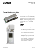
Table Of Contents

Page 2 of 4 Siemens Industry, Inc.
Operator Display Panel II (ODP II)
l Continuous display of hood operating parameters
using a large alpha-numeric display.
l Colored hood status lights for normal (green),
marginal (yellow), and alarm (red) conditions.
l Purge push-button for activation of emergency
operation mode.
l Alarm horn for high and low face velocity and
emergency purge indication.
l Easy to install and connect to the controller via a
single cable and telephone type connectors.
l “Greenleaf” turns red to indicate unsustainable
operation, such as keeping sash open when not in
use. Animated graphics to encourage safe use.
Applications
Operating independently, or integrated with the
Siemens Industry, Inc. control system, the Fume
Hood Controller may be configured for the following
types of laboratory fume hood applications:
l 2940 — 2-position for use with Damper
l 2941 — VAV for use with Damper
l 2942 — VAV for use with Venturi Air Valve or
VFD
WARNING:
The applications cannot detect a broken
wire to the analog input for the second
sash!
The Sash Open Area Module (SOAM) should
be used for all fume hoods with more than
one sash.
Description
The VAV Fume Hood Controller consists of the
following components, which are required for each
fume hood:
l Fume Hood Controller
l Operator Display Panel and Cable
l Sash Sensor Kits (Vertical/Horizontal)
l Hoods with more than 1 sash will require use of
Sash Open Area Module (SOAM)
l Airflow Measurement and Control Options
Works with airflow control devices with electronic or
pneumatic actuation.
Controller
The Fume Hood Controller consists of a control circuit
board and metal enclosure. The enclosure may be
mounted directly on the exterior of the fume hood or
remotely on the laboratory wall or ceiling. The
controller circuit board is snap mounted inside the
enclosure and provides all wiring terminations for
input and output points, 24 Vac power, FLN trunk, and
the Operator Display Panel. A spare digital input and
output are provided for user applications such as
auxiliary sensors and alarms.
The control algorithms are pre-programmed. The
controller is ready to begin operation after selecting
the proper application number defining the network
address, and appropriate setpoint and control
parameters using the laptop terminal. User-definable
parameters include:
l Face Velocity Setpoints:
Unoccupied, Occupied-High, -Medium, -Low
l Alarm and Warning Limits
l Minimum Exhaust Flow
l Maximum Exhaust Flow
l Hood Sash Dimensions
l Control PID Gains
l Display Resolution
l Alarm Delay
l Emergency Setpoint
l Sash Open Area “Alert” for both Attended and
Unattended conditions
The controller uses the measured sash position and
the exhaust airflow to calculate the fume hood face
velocity using the equation:
Face Velocity = Exhaust CFM ÷ Hood Open Area*
*Includes the sash opening, air foil and bypass area
The face velocity is compared to the face velocity
setpoint to calculate the required exhaust flow. The
controller modulates the damper using a floating
output to maintain the required exhaust airflow. VFD
and Venturi Air Valve applications include use of
calibration table and an analog output to take
advantage of the special flow control characteristics of
these devices. The fume hood controller performs this
control algorithm up to 10 times per second to ensure
maximum speed of response to changes in hood sash
upsets. Concurrently, the controller continually
monitors and updates all fume hood points including:
l Face Velocity
l High/Low Alarms
l Exhaust Airflow
l Sash Position
NOTE: Fume hoods with more than one sash require
use of a Sash Open Area Module (SOAM).