
Installation Instructions

Document No. 546-14404
Installation Instru ctions
May 20, 2006
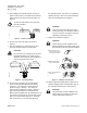
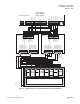
5. After installing all controller boards, verify that
power is OFF. Connect a certified 24 Va c Class II
power s ou rce to the Fume Hood Contro lle r, see
Figure 2.
To meet CE requirements, the enclosure
must be grounded.
FUM0411R1
CONTROLLER POWER WIRING
COMMON
24 VAC HOT
EARTH GND
Figure 2. Power Trunk Wiring.
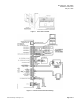
6. Conne ct the FLN trunk wiring as shown in
Figure 3.
7. After all controllers are connected to the FLN
reconnect the FLN trunk to the field panel.
CAUTION:
Do not connect an earth ground to the FLN
trunk shield terminal. The earth ground
should be connected only at the field panel
to prevent ground loop currents.
FUM0412R1
TB2
(SHIELD)(SHIELD)
(+)
(+)
(-)
(-)
Figure 3. FLN Trunk Wiring.
8. Connect the point wiring for the appropriate
Fume Hood Controller application as shown
in F igu re 6. The wiring for vertical sashes is
showninFigure7through. Thewiringfor
horizontal and combination sashes is shown in
Figure 8 through Figure 12. Red/Signal and
Black/Common polarity must be maintained on all
sash sensors. Terminate any unused sash sensor
wires to the sash shield, TB4 pin 12. Terminate
both connection s of a 24 Vac load directly t o
the controller board. The 24 Vac “H” terminal is
switched through a triac to the N O termina tions
when the associated DO is energized.
CAUTION:
The Fume Hood Controller DOs control
24 Vac loads only. The maximum rating is
12 VA for each DO. For higher ratings an
interposing relay must be used.
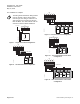
9. Follow the instructions in Figure 4.
CAUTION:
Ferrite filter(s) must be installed on the
Operator Display Panel (ODP) cable. If not,
the controller is not FCC and CE compliant.
TEC0320R3
1- 2 cm
1
Place the filter 1-2 cm
from the end of the cable
or wiring to be shielded.
2
Wind the cable tightly
twice around the filter.
3
Close the filter and wrap
with a zip tie.
Figure 4. Installing a Ferrite Filter.
10.Plug the Operator Display Panel cable into the
Operator Display Panel Communication port on
the controller board (Figure 6 and Figure 5).
CAUTION:
The ferrite filter must b e in stalled on the
cable ins ide the enc losure to mee t FCC
and CE requirements (Figure 5).
Page 2 of 6 Siemens Building Technologies, Inc.