
Installation Instructions

Document No. 546-14404
Installation Instru ctions
May 20, 2006
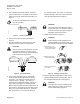
The installation is complete.
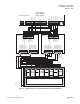
The wiring shown is based on wiring sashes
from the left side. When wiring sashes
from the right, the wiring is reversed. The
sash closest to the connector is wired to
Red and Black. The sash farthest from the
connector is wired to White and Black.
1
2
234
3
TB5
45
56
1
To TB4, PIN 12
78910
CSCSCSCSCS
1
FUM0402R1
White
Black
Red
Figure 7. Single Vertical Sash Configuration.
1
2
234
345
56
1
78910
CSCSCSCSCS
WHITE
WHITE
2
3
REMEMBER TO
CLOSE THE SASH
REMEMBER TO
CLOSE THE SASH
FUM0406R1
RED
RED
BLACK
BLACK
To TB4, PIN 12
TB5
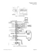
Figure 8. Two Horizontal Sash Configuration.
1
2
234
345
56
1
78910
CSCSCSCSCS
FUM00407R1
2
3
4
5
REMEMBER TO
CLOSE THE SASH
REMEMBER TO
CLOSE THE SASH
REMEMBER TO
CLOSE THE SASH
REMEMBER TO
CLOSE THE SASH
RED
WHITE
WHITE
BLACK
RED
BLACK
TB5
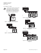
Figure 9. Four Horizontal Sash Configuration.
1
2
234
345
56
1
78910
CSCSCSCSCS
RED
RED
WHITE
BLACK
BLACK
RED
BLACK
FUM0409R1
22
3
REMEMBER TO
CLOSE THE SASH
REMEMBER TO
CLOSE THE SASH
1
WHITE
WHITE
TB5
To TB4, PIN 12
Figure 10. Two Horizontal/One Vertical Sash
Configuration.
1
2
234
345
56
1
78910
CSCSCSCSCS
RED
RED
WHITE
WHITE
WHITE
BLACK
BLACK
RED
BLACK
FUM0408R1
22
3
4
5
REMEMBER TO
CLOSE THE SASH
REMEMBER TO
CLOSE THE SASH
REMEMBER TO
CLOSE THE SASH
REMEMBER TO
CLOSE THE SASH
1
TB5
To TB4, PIN 12
Figure 11. Four Horizontal/One Vertical Sash
Configuration.
Page 4 of 6
Siemens Building Technologies, Inc.