BACnet LCM-OAVS Room Pressurization with Slowacting Venturi Air Valves (One Exhaust, One Supply) and Hot Water Reheat, Application 6752 Application Note 140-1322 2015-07-07 Building Technologies
Table of Contents Overview ............................................................................................................................. 5 BACnet .............................................................................................................................. 6 Auto Discovery ..................................................................................................................... 7 Auto Addressing ......................................................................
Temperature Control Loop ................................................................................................. 31 Alarms ............................................................................................................................ 33 Ventilation Alarm ................................................................................................ 33 Pressurization Alarm ..........................................................................................
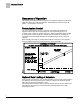
Sequence of Operation BACnet Overview Application 6752 controls pressurization, ventilation, and room temperature in a laboratory room served by one single-duct supply terminal with a reheat coil, one general exhaust terminal, and up to six fume hoods (multiple fume hood flow signals must be averaged using an averaging and scaling module. Pressurization is controlled by maintaining a selected difference between supply and exhaust airflows.
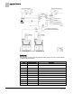
Sequence of Operation BACnet Ventilation and Pressurization Control Drawing. BACnet The controller communicates using BACnet MS/TP protocol for open communications on BACnet MS/TP networks.
Sequence of Operation Auto Discovery Auto Discovery Auto Discovery allows you to automatically discover and identify PTEC/ATEC controllers on the BACnet MS/TP Network. There are two basic configurations: Devices not configured with an address. (Devices are discovered by their unique serial number.) Devices configured with an address and available for modification. Auto Addressing Auto Addressing allows you to automatically assign device addresses to a PTEC/ATEC controller on the BACnet MS/TP Network.
Sequence of Operation Pressurization Control Sequence of Operation The following paragraphs present the sequence of operation for BACnet LCM-OAVS Application 6722: VAV Room Pressurization with HW Reheat and Slow Venturi Air Valves — One Exhaust, One Supply. Pressurization Control The goal of pressurization control is to maintain a fixed difference between the volumes of total supply air and total exhaust air (see the following figure).
Sequence of Operation Room Airflow Balance To deal with the possibility of unequal flow rate changes, the application includes two new points which allow field adjustment to slow down actuators. SUP MAX RATE effectively limits the speed of the supply actuator; GEX MAX RATE effectively limits the speed of the exhaust actuator. SUP MAX RATE and GEX MAX RATE should be changed to values other than 0 only after a thorough analysis has been made of the job specific scenarios.
Sequence of Operation Room Airflow Balance Room Airflow Balance The difference between total supply flow and total exhaust flow is the room airflow balance as shown in these calculations: VOL DIFFRNC = TOTL EXHAUST – TOTL SUPPLY -orVOL DIFFRNC = (HOOD VOL + GEX AIR VOL + OTHER EXH) – (SUP AIR VOL + OTHER SUP) The controller uses these calculations to maintain VOL DIFFRNC at the VOL DIF STPT.
Sequence of Operation Active Flow Minimums and Maximums NOTE: The displayed OCC/UNOCC status of the LCTLR point does not always match the occupancy status of the controller. To get an actual indication of occupancy status, OCC.UNOCC must be used. If network commands are not required and occupancy will be set by sources in the room, set NET OCC CMD to UNOCC. If set to OCC, the controller will stay in occupied mode.
Sequence of Operation VAV versus CV Control When OCC.UNOCC equals UNOCC: The active supply airflow minimum equals UOC SUP MIN. The active supply airflow maximum equals UOC SUP MAX. The active general exhaust airflow minimum equals UOC GEX MIN. The active general exhaust airflow maximum equals UOC GEN MAX. VAV versus CV Control In Application 6752, VAV means that temperature is controlled by varying flow in conjunction with the reheat valve.
Sequence of Operation Flow Tracking – Supply Tracks Exhaust vs. Exhaust Tracks Supply NOTE: If desired, the LCM can be used without any fume hoods attached. In this case, MAX HOOD VOL should be set to 0 cfm to disable the alarming that would occur if the fume hood flow input drops below 1 Vdc. Flow Tracking – Supply Tracks Exhaust vs.
Sequence of Operation Calculating Exhaust Flow Setpoint TRACK METHOD TRACK METHOD is a point associated with TRACK MODE. TRACK MODE determines which airflow (supply or general exhaust) gets tracked and which airflow does the tracking. TRACK METHOD determines how tracking is accomplished. If TRACK MODE is set to ETS and TRACK METHOD is set for FLOW tracking, the general exhaust flow setpoint is calculated according to the measured value, SUP AIR VOL.
Sequence of Operation Calculating Supply Flow Setpoint When Exhaust Tracks Supply (ETS) flow tracking is used, the general exhaust airflow setpoint is calculated the same during both VAV and CV operation, as follows: To calculate GEX FLO STPT, the controller determines the general exhaust airflow value that pressurizes the room based on the values of VOL DIF STPT, OTHER EXH, OTHER SUP and either SUP FLO STPT or SUP AIR VOL depending on the value of TRACK METHOD.
Sequence of Operation Ventilation – VAV Mode Ventilation – VAV Mode During VAV operation, the ventilation works as follows: OCC SUP MIN, the occupied supply minimum, is used to ensure that the room receives enough supply air for proper ventilation during the occupied mode. UOC SUP MIN is used to ensure that the room receives enough supply air for proper ventilation during the unoccupied mode.
Sequence of Operation AVS Calibration AVS Calibration Calibration of the air velocity transducer(s) is periodically required to maintain accurate air velocity readings. Depending on the value of CAL SETUP, calibration takes place either at fixed time intervals or whenever the application goes into unoccupied mode. When calibration is in progress, CAL AIR equals YES. After calibration, CAL AIR returns to NO. The application uses Autozero Modules connected to AUTOZERO DO8.
Sequence of Operation Airflow Control NOTES: 1. Open the door to the controlled space and set VOL DIF STPT must be set to 0 while the flow loops are being tuned. 2. The Venturi Air Valve command points, SUP DMPR AO2 and GEX DMPR AO3, indicate Venturi Air Valve position. Each Venturi Air Valve may be set up for normally open or normally closed operation. 3. Adjusting P gains (supply and/or exhaust) to values greater than 0.1 may cause system instability.
Sequence of Operation Venturi Air Valve Calibration (Mode 1, 3) When general exhaust velocity is greater than 350 fpm, but GEX AIR VOL is less than GEX FLO STPT × LO LIMIT, the table statement and the air velocity feedback loop work together to control the general exhaust air velocity. Once GEX AIR VOL becomes greater than GEX FLO STPT, the air velocity feedback loop suspends operation and the table statement takes over all general exhaust air velocity control.
Sequence of Operation Table Access Feature (Mode 1, 3) NOTE: The factory default values of SUP VLV STAT and GEX VLV STAT is NOTCAL. NOTCAL means that neither the calibration sequence nor manual entry has been done. The value of SUP VLV STAT or GEX VLV STAT is set whenever a calibration or table transfer is performed as the last step of the calibration/table transfer. SUP VLV STAT and GEX VLV STAT are never used for active control decisions.
Sequence of Operation Table Access Feature (Mode 1, 3) Venturi Table Statement Example (active values). a) Supply Venturi Air Valve General exhaust Venturi Air Valve cfm volts cfm volts 598 7.4 618 1.48 777 8.34 712 0.98 861 8.81 760 0.73 980 9.28 800 0.48 1200 10 904 0 These voltage/flow values constitute the “low flow” element (or “point”) for the Supply and the General Exhaust Venturi Air Valves. They are shown here with factory default values.
Sequence of Operation Venturi Table Evaluation and Editing (Mode 1, 3) During calibration, voltage/flow values are automatically generated. Typically there are 8 or 9 pairs. The Venturi Valve actuator is then fed the voltages and the application reads the resulting airflows. At the end of calibration, the airflow readings are analyzed and the calibration is either given a PASS or a FAIL (GEX VLV STAT, or the SUP VLV STAT is set to CAL OK or NOTCAL).
Sequence of Operation Venturi Table Evaluation and Editing (Mode 1, 3) you can decide which one(s) need adjusting. The flow curve should be smooth and incremental. You can change the active values using the following steps: 1. Set V TABLE PT to a “swap” value that tells the application to exchange active table values with inactive table values (see the Table Venturi Air Valve Table Statement for swap value).
Sequence of Operation Venturi Table Evaluation and Editing (Mode 1, 3) The following table lists all values for V TABLE PT and describes their use. Venturi Air Valve Table Statement V TABLE PT Description 0 Default value for V TABLE PT. When V TABLE PT equals 0, changes to TABLE FLOW or TABLE VOLTS are ignored. Setting V TABLE PT to 0 cancels an edit session.
Sequence of Operation PID Only (Mode 2) Venturi Air Valve Table Statement V TABLE PT Description TABLE FLOW and TABLE VOLTS; setting V TABLE PT to 46 will result in the maximum flow and associated voltage for the exhaust Venturi Air Valve to be displayed in TABLE FLOW and TABLE VOLTS. The in between values (33 through 45) are for the range of flow between min and max. NOTE: The table swap will fail if valid flow and voltage values are not entered in Point 46.
Sequence of Operation Open Loop (Mode 3) The Venturi calibration table initially contains all zeros by default, that is, it contains no calibration information. When the application detects a zero flow for the sixteenth entry (the table entry with the highest flow), the application does operate, but runs with only PID control. If PID only control is satisfactory for a given job, there is no need to populate the Venturi tables. Open Loop (Mode 3) This application can operate in open loop mode.
Sequence of Operation Open Loop (Mode 3) It may not be necessary to enter 10.0 values since 10.0 values are initially in the table by default when reverse acting is selected. If specific information about the voltage at low flow is known, that would be entered into Point 1 which is reserved for information about low flow. See Examples 3 and 4 below. Point Flow Volt 1 300 3.0 2 0 0.0 15 0 0.0 16 1200 10.
Sequence of Operation Operating Without a Supply or Exhaust Example 5 - Multi-point Table The point values above are for the exhaust table. Open loop supply operation is similar, but the points used are 1 through 16; not 30 through 46. Since the actual airflow being measured is 0, the heating safety requirement for minimum airflow is not met and heating will not occur.
Sequence of Operation Room Temperature and Setpoint In the open loop mode, the measured airflow is always 0. To re-enable heating, the MODHTG FLO value must be set to 0. When used with an electric reheat, the 0 should be set only after a thorough safety review that shows the electric heating mechanism has sufficient internal safeguards (that is, resettable shutoffs) that would operate if the system actually did have insufficient flow.
Sequence of Operation Room Unit Identification Room Unit Identification For Analog Room Units (Series 1000) – The revision number is visually identified by its case. For Digital Room Units (Series 200/2300 Firmware Revision 25 or earlier) – The revision number displays for 5 seconds when the room unit is first powered up. These room units will display laptop when a laptop is connected and will no longer update room temperature sensor values.
Sequence of Operation PPCL STATUS SENSOR SEL Value * Description 7 Digital Room Unit, RH, CO2, 10K 8 Analog Room Unit, 100K 9 Digital Room Unit, 100K 11 Digital Room Unit, RH, 100K 13 Digital Room Unit, CO2, 100K 15 Digital Room Unit, RH, CO2, 100k 16 (Not used) Example 1: Digital Room Unit with temperature, RH, CO2 and 10K thermistor. 1+2+4+0 = 7 Example 2: Analog Room unit with 100K thermistor. 0+0+0+8 = 8 Room CO2 RM CO2 displays the CO2 value in units of parts-per-million (PPM).
Sequence of Operation Temperature Control Loop Temperature Control Sequence. The range of TEMP LOOPOUT is 0 to 100%. Higher values indicate a need for more cooling (or less heat). The Figure Temperature Control Sequence shows that as the value of TEMP LOOPOUT moves from START to 0%, and the reheat VALVE CMD is modulated from 0 to 100%. VALVE CMD is converted to a voltage and put out on REHEAT A01.
Sequence of Operation Alarms When the controller is operating in the constant volume mode, TEMP LOOPOUT is not allowed to get numerically bigger than the value of START. This means that the application will control the temperature only by modulating the reheat valve; it will make no attempt to control temperature by varying the airflow in the space. During constant volume control, TEMP CTL VOL will remain equal to zero. Alarms The controller is equipped with ventilation and pressurization alarms.
Sequence of Operation Alarms Even if the alarm level is set to zero, the ventilation alarm will still turn on if: SUP AIR VOL stays below the currently active supply minimum, for a time at least equal to VENT ALM DEL. and/or GEX AIR VOL stays below the currently active general exhaust box minimum, for a time at least equal to VENT ALM DEL.
Sequence of Operation Alarms ALARM ENA Values. ALARM ENA 0 No alarms are enabled. default 1 Vent Alarm is enabled. 2 Alarm Switch is enabled. 4 Dif Alarm is enabled. 5 Vent Alarm and Dif Alarm are enabled. 6 Alarm Switch and Dif Alarm are enabled. 7 Vent Alarm, Alarm Switch, and Dif Alarm are all enabled. NOTE: If ALARM ENA is set greater than 7, it will default to 0. ALM ENA is additive.
Sequence of Operation Valve Position on Return from Power Failure Alarms in Open Loop Mode When operating a Venturi valve in open loop mode, there is no sensor to measure actual flow. Instead, flow estimates are based on the current commanded valve position. Valve Position on Return from Power Failure On a return from power failure, the AOs remain OFF for 5 seconds prior to resuming control.
Sequence of Operation Fail Mode Operation AVS FAILMODE values are not additive. For example, if AVS FAILMODE equals 3, this means to open the supply Venturi Air Valve and hold the general exhaust Venturi Air Valve if an AVS fails. The first seven values of AVS FAILMODE (0 through 6) describe specific actions taken when an AVS fails. For example, if AVS FAILMODE equals 5, then whenever an AVS fails, the supply Venturi Air Valve will always close and the general exhaust Venturi Air Valve will always open.
Sequence of Operation Application Notes * If MAX HOOD VOL is set to 0, a “Failed” status of HOOD VOL will not initiate a failure in TOTL EXHAUST or VOL DIFFRNC. See Fume Hood Flow Input.
Sequence of Operation Application Notes Application Notes Supply Only - Operating Without a General Exhaust Box This application can operate without a general exhaust box. If a general exhaust box is not being controlled, set TRACK METHOD to FLOW and set the following points: TRACK MODE to 3. – Without a fume hood attached, use a value of 3 = ETS (exhaust tracks supply) Flow Tracking, should be used for both the occupied and unoccupied modes.
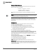
Sequence of Operation Wiring Diagrams Wiring Diagrams Offboard Air Module Wiring. CAUTION The LCM-OAVS has two terminal blocks with terminations numbered identically (terminations 1 through 16). DO NOT mix these up with each other. If the LCM-OAVS is not connected as shown, it is not resistant to electrical surges. It is also susceptible to interference from other equipment. CAUTION A separate power supply is required if a 4-20 mA sensor is used.
Sequence of Operation Wiring Diagrams NOTE: If the voltage/current switch is set to current and a 4 to 20 mA sensor is connected to an AI, then special wiring requirements must be followed. NOTE: The controller’s DOs control 24 Vac loads only. The maximum rating is 12 VA for each DO.
Sequence of Operation Wiring Diagrams BACnet LCM-OAVS Slow Actuation Venturi Supply/Venturi Exhaust – Application 6752 Wiring Diagram. 42 Siemens Industry, Inc.
Point Database Application 6752 Point Database Application 6752 Object Type Object Instance (Point Number) Object Name (Descriptor) Factory Default (SI Units) Eng Units (SI Units) Range Active Text Inactive Text AO 1 CTLR ADDRESS 255 -- 0-255 -- -- AO 2 APPLICATION 6792 -- 0-32767 -- -- AO 3 TEMP OFFSET 0.0 (0.0) DEG F (DEG C) -31.75-32 -- -- AI {04} ROOM TEMP 74.0 (23.44888) DEG F (DEG C) 48-111.75 -- -- AO 5 OCC DIF STPT 400 (188.
Point Database Application 6752 Object Type Object Instance (Point Number) Object Name (Descriptor) Factory Default (SI Units) Eng Units (SI Units) Range Active Text Inactive Text AI {30} GEX AIR VOL 0 (0.0) CFM (LPS) 0-32764 -- -- AO {31} OCC SUP MAX 3400 (1604.46) CFM (LPS) 0-32764 -- -- AO {32} OCC SUP MIN 340 (160.446) CFM (LPS) 0-32764 -- -- AO {33} OCC GEX MAX 1100 (519.09) CFM (LPS) 0-32764 -- -- AO {34} OCC GEX MIN 600 (283.
Point Database Application 6752 Object Type Object Instance (Point Number) Object Name (Descriptor) Factory Default (SI Units) Eng Units (SI Units) Range Active Text Inactive Text AO {67} UOC GEX MAX 1000 (471.9) CFM (LPS) 0-32764 -- -- AO {68} UOC GEX MIN 500 (235.95) CFM (LPS) 0-32764 -- -- AI {69} TOTL SUPPLY 0 (0.0) CFM (LPS) 0-32764 -- -- AO 70 SUP P GAIN 0.015 -- 0-4.095 -- -- AO {71} UOC SUP MAX 2200 (1038.
Point Database Application 6752 Object Type Object Instance (Point Number) Object Name (Descriptor) Factory Default (SI Units) Eng Units (SI Units) Range Active Text Inactive Text AO 105 VENTURI ACT 1 -- 0-255 -- -- AO 106 MODHTG FLO 300 (1.524) FPM (MPS) 0-4095 -- -- AO 107 DO DIR.REV 0 -- 0-255 -- -- AI {108} RM RH 50 PCT 0-102 -- -- AO 109 FAIL TIME 60 SEC 0-510 -- -- AO 117 MINHOODVOLTS 1 VOLTS 0-10.
Point Database (Slave Mode) Application 6792 Point Database (Slave Mode) Application 6792 Object Type Object Instance (Point Number) Object Name (Descriptor) Factory Default (SI Units) Eng Units (SI Units) Range Active Text Inactive Text AO 1 CTLR ADDRESS 255 -- 0-255 -- -- AO 2 APPLICATION 6792 -- 0-32767 -- -- AO 3 TEMP OFFSET 0.0 (0.0) DEG F (DEG C) -31.75-32 -- -- AI {04} ROOM TEMP 74.0 (23.44888) DEG F (DEG C) 48-111.75 -- -- AI {13} ROOM STPT 74.0 (23.
Point Database (Slave Mode) Application 6792 Object Type Object Instance (Point Number) Object Name (Descriptor) Factory Default (SI Units) Eng Units (SI Units) Range Active Text Inactive Text AI {84} AI 5 74.0 (23.496) DEG F (DEG C) 37.5-165 -- -- BO {94} CAL AIR NO -- Binary YES NO AO 95 CAL SETUP 4 -- 0-255 -- -- AO 96 CAL TIMER 12 HRS 0-255 -- -- AO 97 DUCT AREA 1 1.0 (0.09292) SQ. FT (SQ M) 0-6.
Issued by Siemens Industry, Inc. Building Technologies Division 1000 Deerfield Pkwy Buffalo Grove IL 60089 Tel. +1 847-215-1000 Document ID 140-1322 Edition 2015-07-07 © Siemens Industry, Inc., 2015 Technical specifications and availability subject to change without notice.