
Application

Sequence of Operation
AVS Calibration
17
Siemens Industry, Inc.
Application Note, App 6752
140-1322
2015-07-07
AVS Calibration
Calibration of the air velocity transducer(s) is periodically required to maintain accurate
air velocity readings. Depending on the value of CAL SETUP, calibration takes place
either at fixed time intervals or whenever the application goes into unoccupied mode.
When calibration is in progress, CAL AIR equals YES. After calibration, CAL AIR
returns to NO.
The application uses Autozero Modules connected to AUTOZERO DO8. This means
that the supply and general exhaust flow control devices do not close during calibration
of the transducers.
NOTE:
The LCM does not monitor Fume Hood flow changes for 3 seconds during AVS
calibration.
Airflow Control
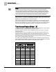
In these applications, the supply and general exhaust Venturi Air Valves can operate in
one of three modes:
Mode 1 – Operates with both a PID loop and a Venturi table.
This mode provides the best control and would be the most commonly used mode
for these applications. In this mode, the embedded Venturi table statements works
together with a PID feedback loop to operate the Venturi air valve so that the
measured air velocity is maintained at setpoint. The following several sections
describe this mode.
Mode 2 - Operates with a PID loop, but no Venturi table.
In this mode, the controller operates with PID control based on a flow sensor input,
but the Venturi table is not used. See the
PID Only Mode
section later in this
document for specific information on this mode.
Mode 3 - Operates with Venturi table, but no PID loop
In this mode, the controller operates open loop (without a flow sensor). There is no
PID control. Positioning of the actuator is based solely on a Venturi table consisting
of command voltages and their resultant corresponding airflows. See the
Open
Loop Mode
section later in this document for specific information on how this mode
differs from the normal Mode 1 above.
Feedback Loop Operation
When the flow is slightly below the setpoint, the controller opens the Venturi Air Valve
slowly, more and more until the airflow reaches the setpoint, at which time the air
valve’s position remains constant. If the flow is far below the setpoint, the controller
opens the Venturi Air Valve rapidly, and rapidly increases until the airflow reaches the
setpoint, at which time the air valve’s position remains constant. The feedback gains
SUP P GAIN and GEX P GAIN are adjusted to tune the flow loops. The sample loop
time for the flow loops is fixed at 0.2 seconds. I and D gain are inherent in the system
and do not need adjustment.