
Application

Sequence of Operation
Venturi Table Evaluation and Editing (Mode 1, 3)
23
Siemens Industry, Inc.
Application Note, App 6752
140-1322
2015-07-07
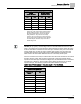
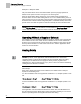
you can decide which one(s) need adjusting. The flow curve should be smooth and
incremental.
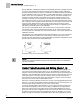
You can change the active values using the following steps:
1. Set V TABLE PT to a “swap” value that tells the application to exchange active
table values with inactive table values (see the Table
Venturi Air Valve Table
Statement
for swap value).
This step is necessary because the application does not allow active values to
be manually overridden.
NOTE:
An exception to this rule is when active values cannot be manually overridden. The
first element in the active portion of the table—the low flow point—can be edited
directly. The Table
Venturi Air Valve Table Statement
explains this in more detail.
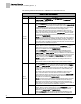
2. Edit the inactive table values.
Since you have just switched the active and inactive portions of the table in
Step 1, the inactive values are now identical to what the active values were
moments ago. You can now edit these new inactive values by using V TABLE
PT to reference them in TABLE FLOW and TABLE VOLTS. The Table
Venturi
Air Valve Table Statement
explains this in more detail.
3. Set V TABLE PT once again to the swap value. This places the newly edited
inactive values back into the active portion of the table statement (again, the active
and inactive portions of the table are simply swapped). However, before the swap
is finalized, the application analyzes your proposed values using the same logic as
in a regular calibration sequence.
⇨
If your proposed values are good, then the swap is made and the edited
values are accepted into the active portion of the table. GEX VLV STAT
is set to CAL OK for exhaust calibration and SUP VLV STAT is set to
CAL OK for supply calibration and control of the Venturi Air Valve
resumes.
⇨
However, if either point is set to NOTCAL, you must gather and view the
voltage/flow values to see where the problem lies.
NOTES:
1. If
SUP FLO COEF is 0, the table edit feature uses a supply flow coefficient of 1.
2. If
SUPDUCT AREA is 0, the table edit feature uses a supply duct area of 1 square
foot.
3. If
GEX FLO COEF is 0, the table edit feature uses a general exhaust flow
coefficient of 1.
4. If
GEXDUCT AREA is 0, the table edit feature uses a general exhaust duct area of
1 square foot.