
Application

Sequence of Operation
Venturi Table Evaluation and Editing (Mode 1, 3)
24
Siemens Industry, Inc.
Application Note, App 6752
140-1322
2015-07-07
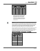
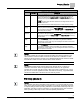
The following table lists all values for V TABLE PT and describes their use.
Venturi Air Valve Table Statement
V TABLE PT
Description
0
Default value for V TABLE PT. When V TABLE PT equals 0, changes to
TABLE FLOW or TABLE VOLTS are ignored. Setting V TABLE PT to 0
cancels an edit session.
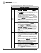
Active
Supply
1
Setting V TABLE PT to 1 takes the flow (cfm) and voltage values from the
first element of the active supply table and displays them in
TABLE FLOW
and
TABLE VOLTS where they can be edited. (This is the only active
supply element (or “point”) that can be directly edited.) Flow and voltage
values are not allowed to exceed those in active supply point 2.
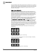
To operate in the range below minimum readable flow (less than 350
fpm), a low flow value in cfm from either the room schedule or the supply
Venturi Air Valve housing is entered into
TABLE FLOW, with the correct
corresponding actuator voltage determined/confirmed by the balancer and
entered into
TABLE VOLTS.
NOTE: This point is only necessary for supply Venturi Air Valve operation
in the range below minimum readable flow (below 350 fpm). Otherwise it
can be ignored. This low flow point must be entered only after other non-
zero points exist in the table as a result of manual edits, or as the result of
a prior Venturi auto calibration sequence.
2 - 16
This portion of the table (2 through 16) can be viewed but not edited
directly. When a point is selected (that is, when
V TABLE PT is set to a
value 2 through 16), the corresponding flow and voltage values are
displayed in TABLE FLOW and
TABLE VOLTS.
Setting
V TABLE PT to 2 will result in the smallest readable flow and
associated voltage for the supply Venturi Air Valve to be displayed in
TABLE FLOW and TABLE VOLTS; setting V TABLE PT to 16 will result in
the maximum flow and associated voltage for the supply Venturi Air Valve
to be displayed in TABLE
FLOW and TABLE VOLTS. The in between
values (3 through 15) are for the range of flow between min and max.
NOTE: The table swap will fail if valid flow and voltage values are not
entered in point 16.
Table entries marked as failed display FAIL for both flow and voltage.
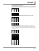
Active
Exhaust
31
Setting V TABLE PT to 31 takes the flow (cfm) and voltage values from
the first element of the active exhaust table and displays them in
TABLE
FLOW and TABLE VOLTS where they can be edited. (This is the only
active exhaust element (or “point”) that can be directly edited.) Flow and
voltage values are not allowed to exceed those in active exhaust point
number 32.
To operate in the range below minimum readable flow (less than 350
fpm), a low flow value in cfm from either the room schedule or the
general-exhaust Venturi Air Valve housing is entered into
TABLE FLOW,
with the correct corresponding actuator voltage determined/confirmed by
the balancer and entered into
TABLE VOLTS.
NOTE: This point is only necessary for general-exhaust Venturi Air Valve
operation in the range below minimum readable flow (below 350 fpm).
Otherwise it can be ignored. This low flow point must be entered only
after other non zero points exist in the table as a result of manual edits, or
as the result of a prior Venturi auto calibration sequence.
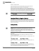
32 - 46
This portion of the table (32 through 46) can be viewed but not edited
directly. When a point is selected (that is, when
V TABLE PT is set to a
value 32 through 46), the corresponding flow and voltage values are
displayed in
TABLE FLOW and TABLE VOLTS.
Setting V TABLE PT to 32 will result in the smallest readable flow and
associated voltage for the exhaust Venturi Air Valve to be displayed in