
Application
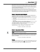

Sequence of Operation
Open Loop (Mode 3)
27
Siemens Industry, Inc.
Application Note, App 6752
140-1322
2015-07-07
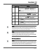
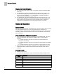
It may not be necessary to enter 10.0 values since 10.0 values are initially in the table
by default when reverse acting is selected.
If specific information about the voltage at low flow is known, that would be entered into
Point 1 which is reserved for information about low flow. See Examples 3 and 4 below.
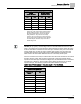
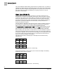
Point
Flow
Volt
1
300
3.0
2
0
0.0
15
0
0.0
16
1200
10.0
Example 3 - Table with Voltage End Limits and Low Flow Value – direct acting
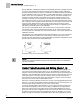
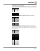
Point
Flow
Volt
1
300
7.0
2
0
10.0
3
0
10.0
15
0
10.0
16
1200
0.0
Example 4 - Table with Voltage End Limits and Low Flow Value – reverse acting
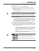
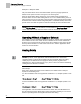
You can also manually populate the table with additional values as shown in Example
5 below. In this case, the table becomes indistinguishable from a table generated using
the calibration process.
Point
Flow
Volt
1
300
3.0
2
0
0
7
0
0
8
340
3.2
9
390
3.5
10
521
3.8
11
531
4.1
12
598
4.9
13
691
5.8
14
798
7.0
15
0
0
16
1200
10