
Application

Sequence of Operation
PPCL STATUS
31
Siemens Industry, Inc.
Application Note, App 6752
140-1322
2015-07-07
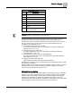
SENSOR SEL
Value *
Description
7
Digital Room Unit, RH, CO2, 10K
8
Analog Room Unit, 100K
9
Digital Room Unit, 100K
11
Digital Room Unit, RH, 100K
13
Digital Room Unit, CO2, 100K
15
Digital Room Unit, RH, CO2, 100k
16
(Not used)
Example 1: Digital Room Unit with temperature, RH, CO2 and 10K thermistor.
1+2+4+0 = 7
Example 2: Analog Room unit with 100K thermistor. 0+0+0+8 = 8
Room CO2
RM CO2 displays the CO
2
value in units of parts-per-million (PPM). RM CO2 (from the
digital 2200/2300 room units) can be used with PPCL in the PTEC/ATEC controller or
unbundled for control or monitoring purposes.
Room RH
RM RH displays the relative humidity value in percent. RM RH can be used for PPCL
in the PTEC or unbundled for control or monitoring purposes.
RM RH displays the relative humidity value in percent.
PPCL STATUS
PPCL STATUS displays LOADED or EMPTY.
LOADED = PPCL - programming is present in the controller. A new application
number must be assigned (12000 through 12999).
EMPTY = NO PPCL - programming is present.
The maximum number of PPCL dynamic points is 15.
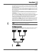
Temperature Control Loop
Whenever the controller is in VAV control mode, the temperature control portion of
Application 6752 works as follows:
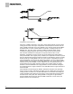
The controller adjusts the supply airflow and the reheat valve as necessary to maintain
CTL TEMP at CTL STPT. (When neither CTL TEMP nor CTL STPT is overridden, this
means the controller tries to maintain ROOM TEMP at ROOM STPT.) The temperature
control loop calculates the value of TEMP LOOPOUT. This value is used to sequence
the cooling flow and the heating valve. See the following figure. The loop is tuned by
adjusting the values of the feedback gains (ROOM P GAIN and ROOM I GAIN and the
sample interval, LOOP TIME.