
Basic Documentation
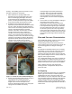
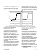
Table Of Contents

Mechanical Pressure
Independence
The brief description of the damper operation
skipped over an interesting characteristic of the
Venturi air valve.
In many valves, the actuator shaft does not directly
move the cone. Instead, they are connected by a
special spring. This gives the cone some freedom to
move along the shaft. The spring exerts a force on
the cone, but so does the air that flows through the
valve. The cone slides along the shaft to the position
where the air pressure balances the spring.
Through this mechanical force balancing process,
the Venturi air valve can be made pressure
independent. That is, as pressures change in the
duct system, the cone moves on the shaft, altering
the airflow path, counteracting the pressure change,
and tending to keep that airflow rate constant. This
behavior depends on a careful mechanical design
that matches the characteristics of the specially
designed, variable-stiffness spring to the shapes of
the cone and the Venturi body.
EXPANDED SPRING --
INCREASED AIRFLOW AREA
LOWER
STATIC
PRESSURE
COMPRESSED SPRING --
DECREASED AIRFLOW AREA
HIGHER
STATIC
PRESSURE
AIRFLOW
REMAINS
CONSTANT
Figure 2. Pressure Independence by the Venturi
Air Valve Pressure Compensation Spring.
Figure 2 illustrates action of the cone and spring.
The upp
er diagram shows, that when a lower static
pressure acts on the upstream side of the cone, the
spring is only slightly compressed, and the cone sits
relatively far out of the throat of the valve. The
resulting airflow area between the cone and Venturi
body allows the required airflow rate.
The lower diagram shows what happens when the
duct pressure increases. Pressure on the upstream
side of the cone pushes the cone along the shaft
(towards the throat) and compresses the spring. This
movement of the cone restricts the airflow,
countering the effect of the pressure increase. The
result is that the airflow rate stays nearly constant.
When the system static pressure decreases, the
cone spring expands and slides the cone back
(away from the throat). This increases the airflow
area and maintains the required airflow rate.
Clearly, this is a sophisticated mechanical device.
Performance depends on carefully selected and
maintained mechanical parameters. Pressure
independent operation is effective over a range of
operating pressures specified for the valve (typically
0.6 in. WC to 3.0 in. WC, 150 Pa to 750 Pa).
Stability of this non-linear, spring-mass system
depends on the shock absorbing effect of the dash
tube (the hollow core of the cone) and the cone
bushing (a spacer that supports the small end of the
cone on the shaft). As the cone moves along the
shaft, it squeezes air through the precise opening
between the bushing and the dash tube wall. This
shock absorber dissipates energy and keeps the
cone from bouncing continually on its spring. Critical
mechanical tolerances allow the cone sufficient
freedom for motion with sufficient damping.
Airflow Control Concepts
Closed Loop Control: The most common approach
to airflow control in a ventilation system is the closed
loop, also called feedback control. By definition,
each adjustment by a closed loop controller depends
on the measured results of previous movements.
1
As the flow controller adjusts the damper (single-
blade, Venturi, or other) it also reads an airflow
sensor to measure the flow rate and compare it to
the desired value (called the setpoint).
If the duct pressure changes, and affects the airflow,
the controller measures that change and quickly
adjusts the damper opening, continuing to sense
airflow until the required rate is restored. This is the
usual way to accomplish pressure independent flow
control.
1. 2005 ASHRAE Handbook - Fundamentals of Control,
Chapter 15, Page 15.1.
Page 2 of 8 Siemens Industry, Inc.
Document No. 1
49-985