
Basic Documentation
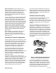
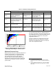
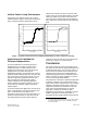
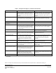
Table Of Contents

accuracy. The following issues are known to cause
mechanical parameters to degrade:
1. With continued use, springs exhibit some
departure from their original spring rate curve
due to material aging and fatigue. Therefore,
mechanical pressure independence is not as
precise, nor will it provide the long-term stability
that is achieved with closed loop flow control.
Page 4 of 8 Siemens Industry, Inc.
Document No. 149-985
2.
Reliable pressure independent operation
depends on precise mechanical clearance inside
the cone, where the dash tube slides back and
forth over the cone bushing. Material from the air
stream is normally deposited on exposed
surfaces in the valve, and over time, can work
into this critical area. Figure 4 shows the
con
dition of several air valves removed from
service. The center left image shows the cone
assembly covered in dust. The bottom left image
shows the cone bushing has been damaged by
deposited material. Because performance is so
sensitive to the condition of these friction
surfaces, a clean air stream improves reliability.
Figure 4. Venturi Air Valves Fouled During Use.
3. Proper valve orientation (horizontal or vertical) is
very important for mechanical pressure
independence. In the vertical position, the
weight of the cone has an impact on the
pressure compensation spring. Thus, the proper
spring must be installed in the factory
corresponding to the position (horizontal or
vertical) in which the valve will be installed.
Therefore, it is mandatory that a Venturi air
valve is installed in the proper horizontal or
vertical position and not in a slanted (angular)
position.
4. The air valve is not only susceptible to fouling of
the precise friction surfaces. Gross
contamination can also upset the open loop
relationship of flow versus position. The images
in the top and bottom right of Figure 4 illustrate
the sort of de
bris that an air valve can catch in
an exhaust system (in this case, large debris).
These valves were removed from service after it
was observed that the airflow did not seem right.
The actuator position signal did not indicate any
problem.
Flow and Pressure Characteristics
The fundamental selection criteria for a flow control
device are the range of flow rates, and
corresponding pressure drops across the device.
These numbers (flow range and pressure range) are
a good starting point for a designer selecting a
device.
It’s important to remember that they are not exactly
comparable. For the Venturi air valve, these values
are the hard limits of the pressure independent
operation. Because these values are hard, physical
limits, prudent designers leave a cushion, and do not
apply the valves right at the limit.
For a single-blade damper, the ranges are based on
a more flexible set of engineering rating criteria. It’s
always possible to push more or less air through the
damper if the effects on the system are acceptable.
Table 1 defines each term and contrasts the
meanin
g between a single-blade damper and a
Venturi air valve.
Air Capacity
Because of the greater airflow area of a single-blade
damper type of air terminal, its airflow capacity is
significantly more than a Venturi air valve of the
same diameter. Since the maximum Venturi air valve
size is typically 12 inches in diameter, larger airflows
require having multiple units arranged in parallel
(ganged together). Figure 5 indicates airflow ranges
of Venturi air
valves and single-blade air terminals of
various sizes.