
Basic Documentation
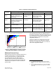
Table Of Contents

SINGLE BLADE
DAMPER
VENTURI AIR
VALVE
AIRFLOW
AREA
AIRFLOW
AREA
(END VIEW) (END VIEW)
Figure 6. Maximum Airflow Areas for the Wide
Open Position.
Figure 6 shows that a blade damper's fully open
airflow a
rea is much greater in comparison to a fully
open Venturi air valve of the same diameter. A fully
open single-blade damper’s airflow area equals the
internal duct area less the area occupied by the
damper shaft. For a fully open Venturi air valve, the
airflow area is limited by the diameter of the cone.
The airflow through a Venturi air valve also changes
direction as it flows around the cone. For these
reasons, a Venturi air valve has a significantly higher
minimum (wide open) pressure drop than a single-
blade damper air terminal of the same diameter.
Typically, a Venturi air valve has a non-recoverable
minimum static pressure drop of 0.6 in. WC (150
Pa). Some manufacturers also offer low pressure
Venturis with a drop of about 0.3 in. WC (75 Pa) In
contrast, the larger airflow area of a fully open
single-blade damper results in a non-recoverable
minimum static pressure drop of about 0.01 to 0.05
in. WC (2.5 Pa to 12.5 Pa).
4
Cost of Static Pressure Loss
The effect of pressure loss on energy consumption
can be complicated, but it doesn’t have to be. Some
lab control publications have confused the issue,
perhaps unintentionally.
5
With the right perspective,
it can be simple.
There are many mathematical ways to express the
power that a fan consumes in a ventilation system.
For this purpose (calculating the effect of pressure
Page 6 of 8 Siemens Industry, Inc.
Document No. 149-985
4. For single duct supply air terminals the pressure drop of the
reheat coil must also be considered when selecting and
sizing air terminals for a given application.
5. For more information, contact Systems Applications in
Buffalo Grove.
losses for a given airflow rate) the following equation
applies:
EfficiencyFan
ssurePreFanAirflow
PowerFan
This means fan power is directly proportional to
pressure loss: twice as much pressure consumes
twice as much power.
If a fan system runs at 5 in. WC of pressure, and we
can save 0.5 in. WC by selecting more efficient
terminals, that saves 10% of the fan power. If the
system is more efficient (for example, 3.0 in. WC)
the percentage savings achievable at the terminals
is even greater.
Some lab control publications mistake the valve
pressure drop for the:
1. Static pressure measured at the terminal. If
a system runs with 0.5 in. WC (125 Pa) at
the terminal, that includes the drop across
other components, not just the valve.
2. Signal pressure generated by the airflow
sensing element. The sensing pressure is
not a loss in the system, and is often many
times greater than the drop across the
valve.
Airflow Sound
When airflow through a device causes a pressure
drop, that energy is dissipated as heat and sound.
The heat component of this energy transformation
causes a slight rise in the air temperature flowing
through the device, but this is usually small and is
disregarded for practical purposes. However, the
sound component can be significant and annoying.
Therefore, sound ratings are an important
consideration when choosing air terminals. A Venturi
air valve terminal will typically create somewhat
more discharge and radiated sound power for a
given airflow than a single-blade damper type of an
air terminal due to its greater pressure drop for a
given airflow.
6
6. Determining the resulting room sound level caused by HVAC
component sound can be a very complex matter. Aside from
the air terminal sound, many other factors affect the room's
ambient sound level. For additional insight into ventilation
related sound, see the Technology Report No. 5 Attaining
Acceptable Ventilation Related Sound in Laboratory Rooms
(149-979) and to Siemens’ comprehensive Application Guide
Minimizing Excessive Sound in Ventilation System Designs
(125-1929).